Countermeasures
AN/ALE-40 Countermeasures System
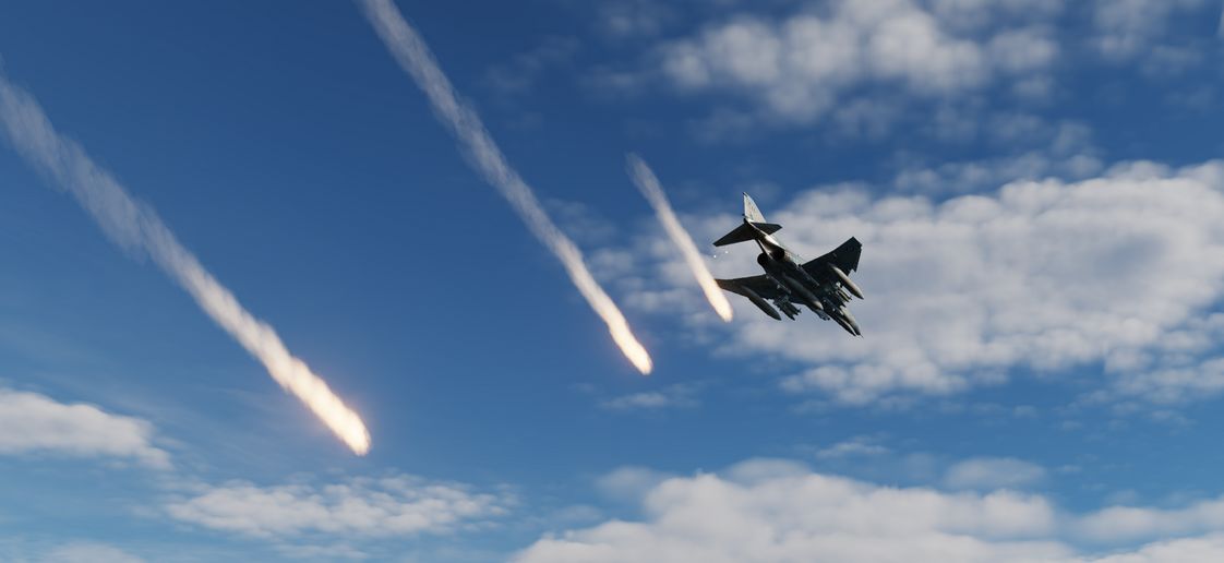
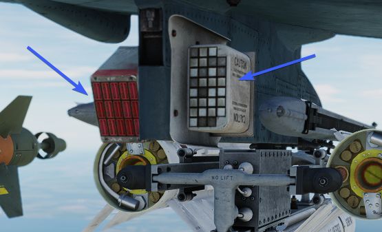
The AN/ALE-40 countermeasures dispenser set provides the capability of dispensing RR-170 A/AL chaff cartridges and MJU-7/B infrared flare cartridges. The system consists of four dispenser slots located on the inboard armament pylons (2 on each) as well as cockpit controls.
The pilot cockpit contains a programmer, a flares select switch with two lamps and a dispense button located on the throttle. The WSO pit has a cockpit control unit (CCU).
The main circuit breaker for the AN/ALE-40 is located on the No. 4 Circuit Breaker Panel above the aft left console in the WSO cockpit.
| Dispenser Configuration | Description |
|---|---|
| No payload | Dispensers installed without payload |
| 120 chaff | Only chaff loaded |
| 60 chaff + 30 flare | 60 chaff and 30 flares loaded |
| 90 chaff + 15 flare | 90 chaff and 15 flares loaded |
| 30 flare | Only flares loaded |
General operation
Operation of the AN/ALE-40 is controlled from both the front and rear cockpit. The CCU initiates the various modes of operation. The programmer will generate the firing commands in different combinations.
The pylon mounted dispensers will convert the firing commands to individually sequenced firing signals. If the operation mode is set to chaff, the dispensing will start in the left pylon dispenser and then transfer the dispensing signals to the right pylon dispenser upon depletion of stores in the left dispenser. If the operation mode is set to flare, dispensing will start in the right pylon master dispenser and upon depletion of stores the sequencer switch will transfer the dispensing signal to the left master dispenser. Flares can also be jettisoned from their dispensers at a rate of 10 flares per second by activating the ripple switch located on the CCU.
Dispensing of countermeasures can be initiated by either the pilot (Button on the Throttle) or the WSO (Dispense Button or Ripple Switch on the CCU).
Countermeasures will be dispensed according to Flares Select Switch, CCU and Programmer settings.
They are two important definitions to know when setting up the countermeasures:
- BURST - single dispense signal
- SALVO - group of bursts
💡 To dispense countermeasures, flaps and speed brakes have to be retracted.
Cockpit Control Unit (CCU) - WSO Cockpit
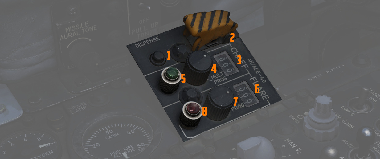
The Cockpit Control Unit (CCU) is installed on the left console of the rear cockpit. It consists of two mode knobs, two counters and two indicator lights (one for chaff and one for flare), as well as a guarded ripple switch and a dispense button.
The CCU issues signals which are sent to the programmer or directly to the dispensers, depending on selected modes.
Chaff Mode Knob
With the chaff select switch (
- OFF - No dispenses, as the chaff system is inactive.
- SGL - A single chaff is dispensed.
- MULT - Chaff dispensed according to CHAFF BURST settings of the Programmer.
- PROG - Chaff dispensed according to CHAFF BURST and CHAFF SALVO settings of the Programmer.
💡 When Chaff Double mode is selected in the Mission Editor, twice as many chaff will be released in every mode (2 chaff for every single chaff dispense signal). The counter is then set to half the number of total chaff cartridges loaded to indicate the number of remaining dispenses, i.e. not the cartridges.
Flare Mode Knob
With the flare select switch (
- OFF - No dispenses, as the flare system is inactive.
- SGL - A single flare is dispensed.
- PROG - Flares dispensed according to FLARE BURST settings of the Programmer.
Chaff and Flare Counters
There are two subtraction counters (3 and 6), one for the chaff system and one for the flare system. They indicate the quantity of remaining chaff and flare cartridges.
Chaff and Flare Indicator Lights
Both the flare and the chaff system have one green indicator light (5 and 8) each. Whenever a mode (other than OFF) is selected on the respective mode knob, the corresponding indicator light will illuminate.
💡 Both chaff and flare can be used simultaneously provided a mixed chaff and flare loadout is used.
Ripple Switch
The ripple switch (
Dispense Button
The dispense button (
Programmer - Pilot Cockpit
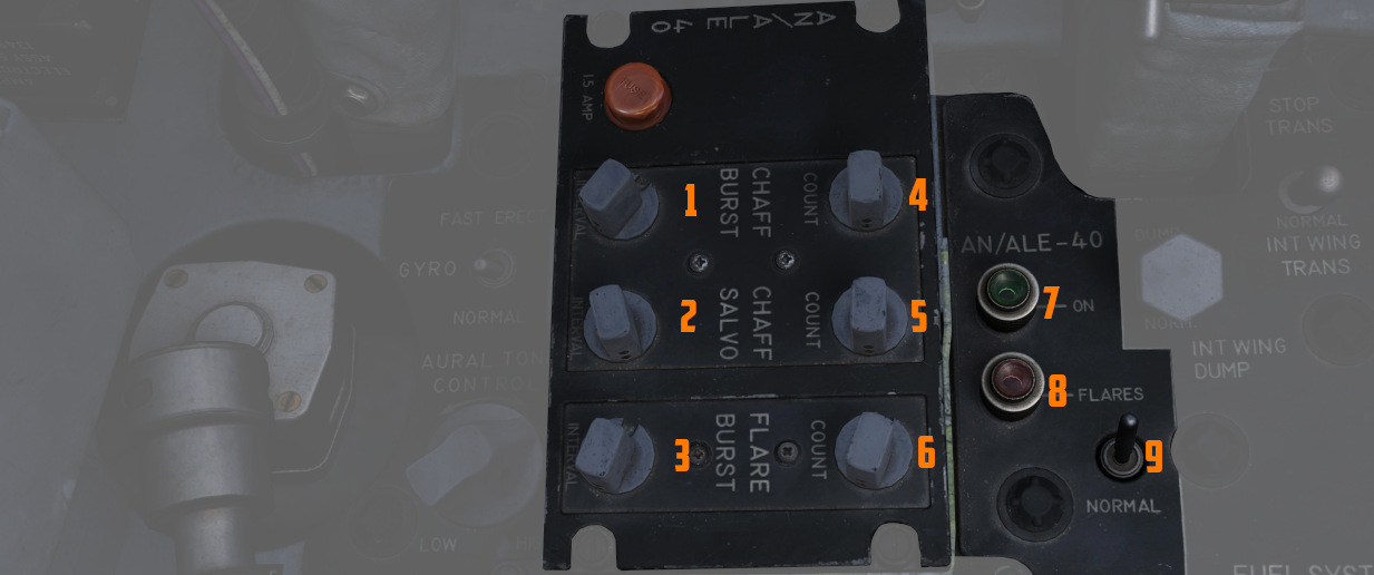
The AN/ALE-40 Programmer contains the controls and circuitry used to send specific fire commands to the chaff and flare dispensers. The following settings are adjustable:
| Category | Knob | Values | Description |
|---|---|---|---|
| CHAFF BURST | COUNT ( | 1, 2, 3, 4, 6, 8 | quantity of bursts (per salvo) |
| INTERVAL ( | 0.1, 0.2, 0.3, 0.4 | time interval between each burst | |
| CHAFF SALVO | COUNT ( | 1, 2, 4, 8, C (continuous) | number of salvos |
| INTERVAL ( | 1, 2, 3, 4, 5, 8, R (random) | time interval between each salvo | |
| FLARE BURST | COUNT ( | 1, 2, 4, 8, C (continuous) | quantity of bursts |
| INTERVAL ( | 3, 4, 6, 8, 10 | time interval between each burst |
💡 All intervals are expressed in seconds.
Fuel System Control Panel - Pilot Cockpit
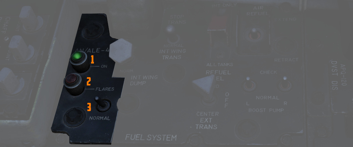
Flares Select Switch
If the flares select switch (
If the flares select switch is in the FLARES position it only affects the front cockpit dispense button by ignoring all switches and knobs in the countermeasures system, provided that the flaps and speed brakes are retracted. This allows the pilot to dispense a single flare each time he presses the dispense button. Rear cockpit dispense functions are unaffected by the switch position.
AN/ALE-40 Power On Indicator Light (Green)
This green light illuminates (
Flares Indicator Light (Amber)
This amber indicator (
When illuminated, flares can be dispensed by pressing the front cockpit dispense button regardless of programmer and CCU settings.
Dispense Button (Pilot Cockpit)
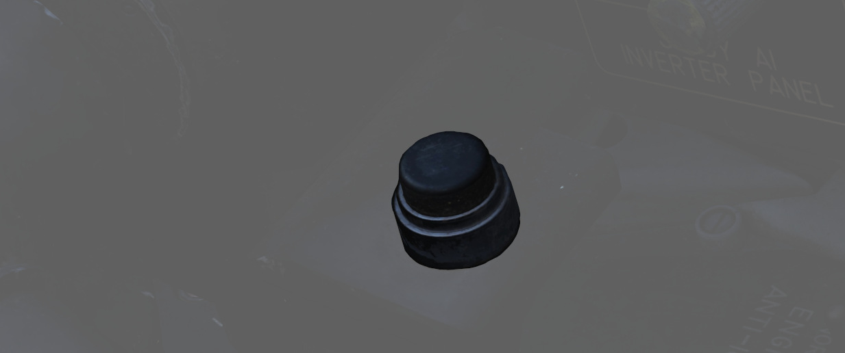
When pressing the dispense button chaff/flare dispensing is initiated as set on the CCU and AN/ALE-40 programmer if the flaps and speed brakes are retracted and the flares select switch is set to NORMAL. Additionally single unit flare dispensing can be initiated by a single button press if the flares select switch is set to FLARES.
AN/ALE-40 Dispensers

The AN/ALE-40 countermeasures dispensers are divided into two distinct dispenser configurations. The master (outboard) dispenser contains the electronics and sequencer switch for both dispensers on each pylon and is installed on the outboard side of the inboard armament pylons. The slave (inboard) dispenser is installed on the inboard side of the inboard armament pylons and is connected to the master dispenser by an interconnect cable. The aircraft can be configured either with four chaff payload modules on all four dispensers or two chaff payload modules on the slave dispensers and two flare payload modules on the master dispensers. Only chaff payload modules can be installed on the slave dispensers; flare payload modules can only be installed on the master dispensers.
Master Dispenser Assembly
💡 Operation of the master dispenser assembly is done automatically by the ground crew in DCS, according to the AN/ALE-40 loadout selected in the loadout menu.
One master dispenser assembly is installed on the outboard side of each inboard armament pylon. It consists of a sequencer switch, a breech assembly, a RESET/OPERATE circuit breaker switch, a payload control switch, a safety pin switch with safety pin and warning streamer and relevant electrical circuitry. The sequencer switch converts the firing commands into individual firing signals for each pyrotechnic squib in both the master and slave dispensers. The breech assembly provides the interface to mount the chaff or flare payload modules. Insertion of the safety pin removes electrical power to both pylon mounted dispensers. After a full chaff or flare module has been loaded, the RESET/OPERATE switch is placed in OPERATE. The chaff or flare sections will fire in sequence. After flight, if a partial load of chaff or flares remains, the switch should be left in OPERATE. If the switch is moved to RESET, the empty chaff or flare stations have to be stepped through before loaded stations will fire. The payload selector switch positions C (chaff) and F (flare) only define the master dispenser mode of deployment and are set automatically in DCS according to the selected loadout.
Slave Dispenser Assembly
💡 The payload selector switch position is by default set to CS (chaff single dispense). However, it can also be set to CD (chaff double dispense via the Mission Editor.
One slave dispenser assembly is installed on the inboard side of each inboard armament pylon. It contains a payload selector switch to set either chaff single or chaff double dispense, a breech assembly and relevant electrical circuitry. If the payload selector switch is left in the default CS position, one chaff cartridge will be dispensed for each chaff burst commanded. If the payload selector switch is set to the CD position, two chaff cartridges will be dispensed simultaneously, one from each dispenser, for each chaff burst commanded. The breech assembly provides the interface to mount the chaff payload module.
Flare Housing Adapter
The flare housing adapter is installed between the master dispenser assembly and the flare payload module. The wedge shaped adapter ensures that the flares will be ejected aft and down from the aircraft. It cannot be mounted to the slave dispenser.
Chaff Payload Module and Cartridges
The chaff payload module is attached to the master or slave dispenser breech assembly with four quick release fasteners. The chaff cartridge consists of a basic plastic sleeve, chaff dipoles and a plastic end cap. When dispensed the chaff dipoles are ejected from the sleeves and leave the disposable sleeve and empty squib case behind. The cartridge base provides a recess for the chaff pyrotechnic squib.
🔴 WARNING: Accidental discharge of chaff cartridges can cause injury to personnel or damage to the aircraft.
Flare Payload Module and Cartridges
The flare payload module can only be installed on the master dispenser assembly. The flare housing adapter serves as the interface. The flare cartridge consists of a metal outer sleeve, a flare element, a safe-ing and initiation device and a plastic end cap. An indentation in the cartridge base allows for proper flare installation.
🔴 WARNING: Accidental discharge of flare cartridges can cause injury to personnel or damage to the aircraft.
Chaff/Flare Pyrotechnic Squibs
The chaff pyrotechnic squibs are installed immediately prior to use and are stored separately from the chaff cartridges. They are metal encased and electrically fired.
The flare pyrotechnic squibs are larger in diameter and have an O-ring groove. They are installed immediately prior to use and are stored separately from the flare cartridges.