VOR/ILS System
![]()
The VHF omnidirectional range instrument landing system, or VOR/ILS, provides precise bearing and course deviation information from a transmitting ground station. Additionally, the aircraft is able to use precision landing approach and descent capabilities at localizer equipped fields. Guidance information from the VOR/ILS system is provided to the pilot on the BDHI, ADI, and HSI. VOR/ILS function is enabled on these displays using the appropriate Flight Director Group control selections on the Bearing/Distance Selector switch, the Navigation Mode Selector switch, and the Flight Director Switch.
ILS System
The ILS system is designed to detect deviations from the designated landing approach path and relay this information to selected avionics in the aircraft.
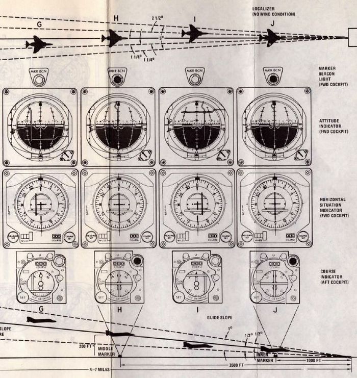
When the appropriate ILS mode is selected on the Navigation Function Selector Panel, several instruments provide guidance for precision approach. These include the Deviation Indicator on the Horizontal Situation Indicator (HSI), which shows lateral alignment with the runway, and the Glide-slope Indicator on the ADI, which displays the vertical descent angle relative to the ideal glide path.
Additionally, if the Flight Director is activated, steering cues will be provided by the needles on the Attitude Director Indicator (ADI), offering visual guidance for both pitch and roll to maintain the correct approach path.
In the rear cockpit the both horizontal and vertical deviations are presented on the Course Indicator.
The typical maximum deviations are ±2.5 degrees for the localizer and ±0.7 degrees for the glide-slope.
Marker Beacons
If Marker Beacons are positioned along the approach path, the aircraft's system will audibly signal and illuminate the corresponding Marker Beacon light as it passes over each one. Depending on the specific setup at an airport, there can be:
- Outer Marker: Identified by a low-pitched, continuous tone.
- Middle Marker: Recognized by a higher-pitched, alternating audio tone. This marker indicates a closer proximity to the runway, usually at the decision altitude for landing.
- Inner Marker: Characterized by a very high-pitched tone or a series of high-pitched dots. This marker is not always present but, when it is, signifies an even closer position to the runway end.
VOR/ILS Control Panel

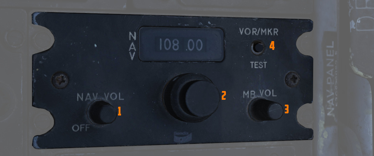
The control panel for the VOR/ILS is found on the front cockpit left console;
the panel includes a frequency indicator, two frequency select knobs (
VOR/ILS Frequency Selector Knobs
The Frequency Selector Knob (

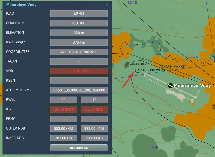
In DCS, to find the desired VOR/ILS frequency of your target, go on the Map and click an airfield that you want to fly to. If available, VOR and ILS frequencies will be listed.
💡 Not every airfield has a VOR station or an ILS systems.
The system is designed to automatically detect whether a tuned frequency corresponds to a VOR station or an ILS localizer. VOR operates within a frequency range of 108 MHz to 117.95 MHz. The ILS localizer frequency range is from 108.1 MHz to 111.95 MHz.
In the shared frequency region, VOR stations typically operate on frequencies with an even-numbered tenth of the range (e.g. 108.2 MHz, 108.4 MHz, etc.), while ILS localizer frequencies are assigned to the odd-numbered tenths, including hundredths of a MHz (e.g. 108.1 MHz, 108.3 MHz, 108.35 MHz, etc.).
The glide-slope component of the ILS operates in a frequency range from 329.3 MHz to 335.0 MHz. These frequencies are paired with their corresponding localizer frequencies, ensuring that there is no need for separate manual setting. When a localizer frequency is selected, the associated glide-slope frequency is automatically tuned, providing integrated lateral and vertical guidance (if available) for precision approaches. The Marker Beacon that works in conjunction with the ILS system, operates at a frequency of 75 MHz.

VOR/MKR Test Pushbutton
After an ILS frequency has been selected on the frequency indicator, pressing the VOR/MKR Test
pushbutton (
NAV VOL Knob and MB VOL Knob
The NAV VOL knob (
WSO Course Indicator

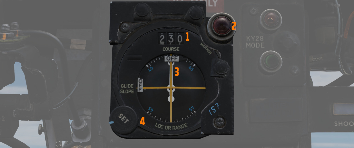
In the rear cockpit is the Course Indicator, on the main instrument panel; During an ILS approach, the indicator displays relative heading for the course set in the course selector window, as well as horizontal and vertical position relative to the ILS localizer and glide slope entered by the pilot. In this way, the WSO can assist the pilot in achieving and maintaining glide slope. The controls for the indicator are purely for the WSOs reference, and do not interact with the Flight Director Group displays in the front cockpit.
Components of the course indicator are a TO-FROM indicator (does not function with ILS), a course deviation scale, a glide slope deviation scale, a COURSE selector window, a course SET knob, a heading pointer and heading scale, a marker beacon light, a GLIDE SLOPE indicator, a course deviation indicator (LOC OR RANGE), and course and glide slope OFF warning flags.
Once the pilot has selected an ILS frequency, the WSO must set a course inbound heading in the selector window using the SET knob.
Used only with the ILS system (doesn't function with VOR).