Radar Air-to-Air Bits
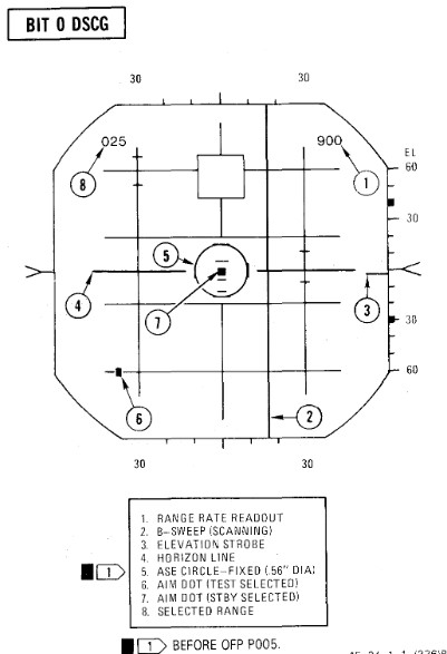
BIT 0 Aim Dot and Range Rate Calibration
| Step | System | Action |
|---|---|---|
| 1. | Radar Power Knob | STBY |
| 2. | DSCG Mode Knob | RDR BIT |
| a. Test Grid | Aligned ±1/16 inches | |
| 3. | Test Knob | DOT BAL and HOLD |
| a. Aim Dot | Centered | |
| b. Range Rate | ±20 knots | |
| 4. | Radar Power Knob | TEST |
| 5. | Test Knob | DOT BAL and HOLD |
| a. Aim Dot | In Calibration Area | |
| b. Range Rate | 900 ±50 knots | |
| 6. | Adjust Horizon Line | Zero Pitch |
| 7. | Radar Range Knob | AI 10 |
| 8. | DSCG Mode Knob | DSCG TEST |
| a. Search Display | Eight Shades of Gray | |
| b. Adjust BRT | Optimal | |
| c. Adjust CONTR | Optimal | |
| 9. | DSCG Mode Knob | RDR BIT |
| 10. | Radar Range Knob | AI 25 |
| 11. | Position EL Strobe | 30° Down |
| (Prevents radar antenna from hitting stops) | ||
| 12. | Stab Switch | OUT |
| a. Horizon Line | Removed | |
| 13. | Stab Switch | NOR |
| 14. | Radar Power Knob | STBY |
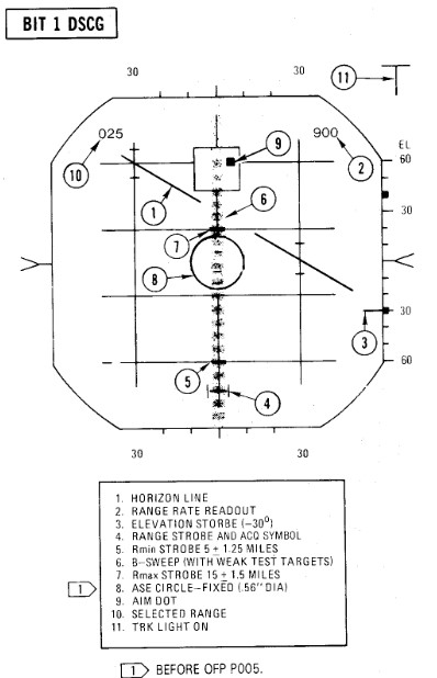
BIT 1 Minimum Discernible Signal, Lockon Sensitivity, Range Track Memory
| Step | System | Action |
|---|---|---|
| 1. | Test knob | Set 1 |
| 2. | Radar power knob | TEST |
| a. Monitor meter (RDR MAG) | Indicates 1.4 to 1.8. | |
| b. Horizon line | Within limit markers as shown. | |
| 3. | Adjust indicators | For optimum contrast (CONTR) and brightness (BRT). |
| a. Minimum targets | 11 targets visible in search. | |
| b. Position range knob | To 5, 10, 50, 100, 200, and 25 while checking video. | |
| 4. | Place acquisition symbol beyond the last target. | |
| 5. | Move range strobe down while holding full action. | |
| a. Range strobe locks on before passing seven targets. | ||
| b. Maintain lockon for 5 seconds. | ||
| 6. | Test knob | Set 0 |
| a. System unlocks in 4 to 6 seconds. | ||
| 7. | Test knob | Set 1 |
| 8. | Pulse switch | SHORT |
| a. Monitor meter (RDR MAG) | Indicates 0.9 to 1.15. | |
| b. Minimum targets | Eight targets visible in search. | |
| 9. | Place acquisition symbol beyond the last target. | |
| 10. | Move range strobe down while holding full action. | |
| a. Range strobe locks on before passing eight targets. | ||
| b. Maintain lockon for 5 seconds. | ||
| 11. | Test knob | 0 for 3 seconds then select TEST 1 |
| a. System goes into memory for 3 seconds, then re-acquires lockon. | ||
| b. Range rate readout flashes at 4 HZ for 3 seconds. | ||
| 12. | (P) Radar missile power | STBY FOR 1 MINUTE |
| 13. | (P) Radar missile power | CW ON |
| a. RDR light | ON STEADY 1 MINUTE | |
| 14. | Meter selector | KLY |
| a. Meter reads | 0.25 to 1.25 | |
| 15. | Lock on third target | |
| a. Aim dot in box | ||
| b. Range rate 900 ±200 knots | ||
| c. Break lock |
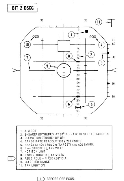
BIT 2 Range Track Acceleration, Antenna Position
| Step | System | Action |
|---|---|---|
| 1. | Test knob | Set 2 |
| 2. | Lock on 10th target | |
| a. System breaks lock in less than 30 seconds. | ||
| 3. | Lock on second target | |
| a. System maintains lock for at least 30 seconds. | ||
| b. Range rate readout 900 ±200 knots | ||
| 4. | Break lock | |
| 5. | Pulse switch | AUTO |
| BEACON CHECK | ||
| 6. | Radar mode knob | BEACON |
| a. BIT targets disappear and at least one beacon target reappears. | ||
| 7. | Radar mode knob | MAP |
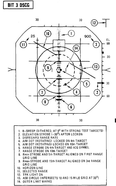
BIT 3 Angle Track
| Step | System | Action |
|---|---|---|
| 1. | Test knob | Set 3 |
| a. B-sweep and EL strobe at 0 ±0.2° (before lockon). | ||
| 2. | Lock on fourth target | |
| a. Aim dot rotates between ASE circle and the segmented circle (not exceeding either by more than 1/4 inch). | ||
| b. Rmax and Rmin at 15 and 5 miles. | ||
| c. ASE circle as shown. | ||
| d. EL strobe goes 30° down (after lockon). | ||
| 3. | Break lock and lock on 10th target | |
| a. Aim dot rotates inside ASE circle. | ||
| 4. | Maintain lockon for BIT 4. |
BIT 4 HOJ, Angle Track Memory, AOJ, Pseudo & Simulated Doppler, Corridor Scan
| Step | System | Action |
|---|---|---|
| 1. | Test knob | Set 4 (figure a). |
| a. All BIT targets disappear but lockon presentation remains. | ||
| b. H light ON | ||
| c. Range rate readout flashing, indicates 900 ±.200 knots, and last digit is replaced with the letter H. | ||
| 2. | (P) Radar missile power switch | OFF (or when AIM-7 missiles are turned). |
| 3. | Position B-sweep and EL strobe | At 0° for reference. |
| 4. | Radar power knob | STBY. |
| a. B-sweep and EL strobe drift less than +5° before unlock. | ||
| 5. | Radar power knob | TEST. |
| 6. | Action switch | FA (figure b). |
| a. AOJ display appears. | ||
| b. Range rate readout disappears And H light OFF. | ||
| 7. | Track switch | AOJ OUT. |
| a. System returns to search. | ||
| 8. | Track switch | AUTO. |
| 9. | Display | VI. |
| a. B-sweep covers 3 bars on selected CAA corridor. | ||
| b. EL-strobe scans from -21° to +57°. | ||
| 10. | Display | B-wide. |
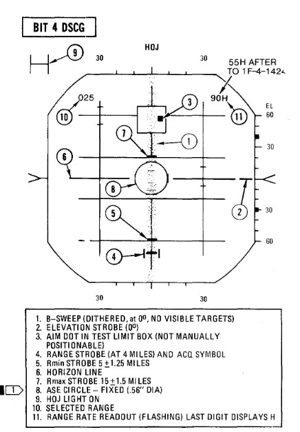 Figure a
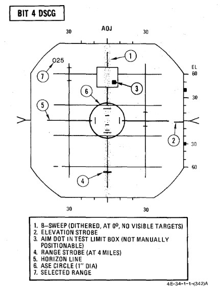 Figure b
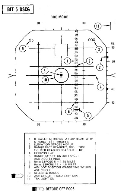
BIT 5 Range Rate Noise, PLMS, CAA
| Step | System | Action |
|---|---|---|
| 1. | Test knob | Set 5 |
| 2. | Lock on third target | |
| a. Range rate readout 0 ± 300 knots. | ||
| b. Aim dot inside of ASE circle. | ||
| c. ASE circle 0.56 inch diameter. | ||
| 3. | Break lock | |
| 4. | Pulse switch | SHORT |
| 5. | (P) Sight mode knob | A/A |
| 6. | Radar mode knob | BST |
| 7. | Range knob | AI 5 |
| 8. | (P) Auto acq button | PRESS and RELEASE |
| a. Radar locks on first target | ||
| 9. | (P) Auto acq button | PRESS and RELEASE |
| a. Radar breaks lock, range gate sweeps to next target and locks on. | ||
| b. Repeat this step through all targets. | ||
| 10. | Air-to-air button | PRESS |
| a. Air-to-air light | OFF | |
| b. Radar control transfers to RCP. | ||
| 11. | Break lockon | |
| 12. | Radar mode knob | MAP |
| 13. | Range knob | AI 25 |
| 14. | Pulse switch | LONG |
| 15. | Lock on fifth target | |
| a. RDR MAG indicates 1.4 to 1.8. | ||
| 16. | Pulse switch | AUTO |
| a. RDR MAG indicates 0.9 to 1.15 (PLMS). | ||
| 17. | Aspect knob | TAIL |
| a. Range rate readout displays fighter heading (0°-360°) | ||
| 18. | Display knob | VI |
| a. Updates fighter heading display. | ||
| 19. | Display knob | B-WIDE |
| a. Discontinues fighter heading update. |
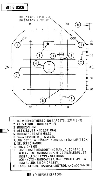
BIT 6 AIM-7 Attack Display and Interlocks
| Step | System | Action |
|---|---|---|
| 1. | Test knob | Set 6 |
| The T (track) light illuminates but SKIN TRK light remains OFF during this test. This is a normal indication with the DSCG. | ||
| 2. | Radar power knob | TEST |
| 3. | Missile power switch | STBY |
| 4. | Position range strobe | Beyond 15 miles. |
| a. Rmax at 15 ± 1.5 miles, Rmin at 5 ± 1.25 miles. | ||
| Range rate 000 knots Indicates AIM -7E missiles/plugs installed or stations empty. 900 knots indicates AIM-7F missiles/plugs installed. After OFP P005, the OFP version number will be displayed for the first 10 seconds in place of range rate readout; for example, OFP version P005 will be approximately 500 knots. | ||
| 5. | Move range strobe down | (with half action or full action) |
| a. Aim dot stationary inside box. | ||
| b. HOLD ALT light ON beyond 15 miles, OFF at 15 miles. | ||
| c. IN RANGE and SHOOT lights ON when range strobe is between Rmax and Rmin. | ||
| d. ASE circle remains fixed in size. | ||
| e. Break X occurs, ASE Circle and range rate readout disappear, IN RANGE/SHOOT lights OFF at 5 miles or less. | ||
| 6. | Radar power knob | STBY |
