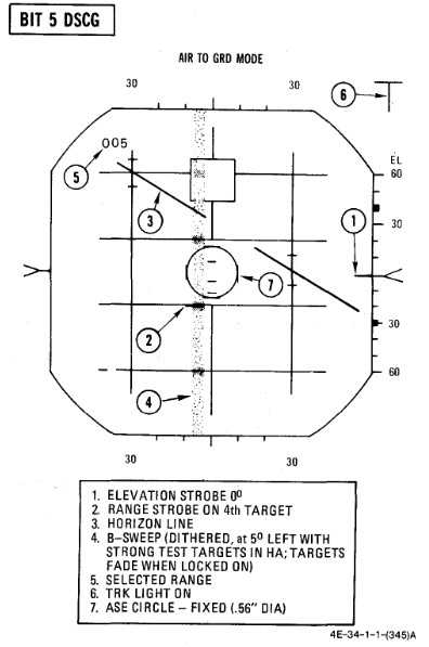
| 1. | (P) Sight mode knob | A/G |
| 2. | Radar power knob | TEST |
| 3. | Radar range knob | AI 5 |
| 4. | Radar mode knob | A/G |
| 5. | Test knob | 5 |
| a. Monitor (RDR MAG) 0.9 to 1.15 | |
| b. B-sweep 5° ±3° left of center. | |
| c. Acquisition symbol centered on B-sweep (before lockon). | |
| d. Horizon line indicates 30° left bank and 30° dive. | |
| 6. | Lock on first target | |
| a. ASE circle appears and B-sweep fades (AGC). AGC action reduces the B-sweep intensity and the weaker test targets fade. However, it is not abnormal for the stronger test targets to be visible in the B-sweep. | |
| b. (P) Range bar at 5:00 within ±.5° (6000 feet). | |
| 7. | Lock on second target | |
| a. (P) Range bar at 3:00 within ±.5° (12,000 feet). | |
| 8. | Lock on third target | |
| a. (P) Range bar at 1:00 within ±.5° (18,000 feet). | |
