Other
Stowing
After turning on the system, the pod can be un-stowed by pressing the STOW push button.
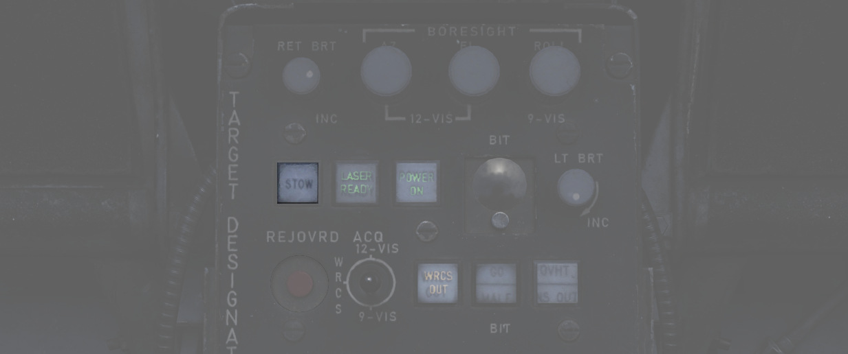
When un-stowed, the pod moves according to the current selections and automatically goes into the WIDE FOV.
In the stowed position, the camera is rotated upwards and a cover is moved in front of it. This protects the camera from stones and other hazards during taxi, takeoff or low level flight.
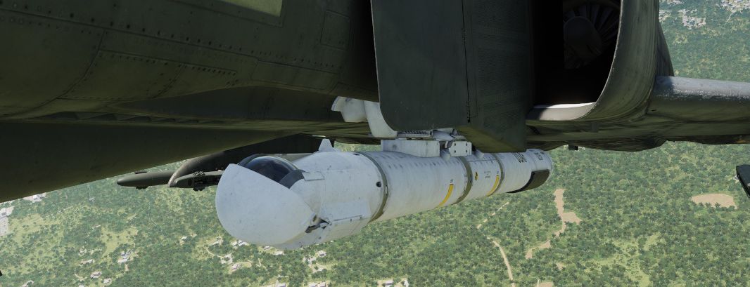
The stow-procedure takes about 5 seconds, with the light indicating the current status.
🟡 CAUTION: The stow-position is held electrically and can not be held without power. Un-powered, the pod swings freely with force. Taking off without first applying power to the pod, or flying with the pod being powered off, will cause the pod to leave the stow position. Outside of the stow position, the system will get damaged through hazards and whenever it is forcefully moved into its gimbal limits. Damage will not only offset the boresight position, but also affect other properties, such as movement speed and similar.
Cooling
The targeting pod has a cooling system installed in the rear section, which automatically cools the pod by external airflow.
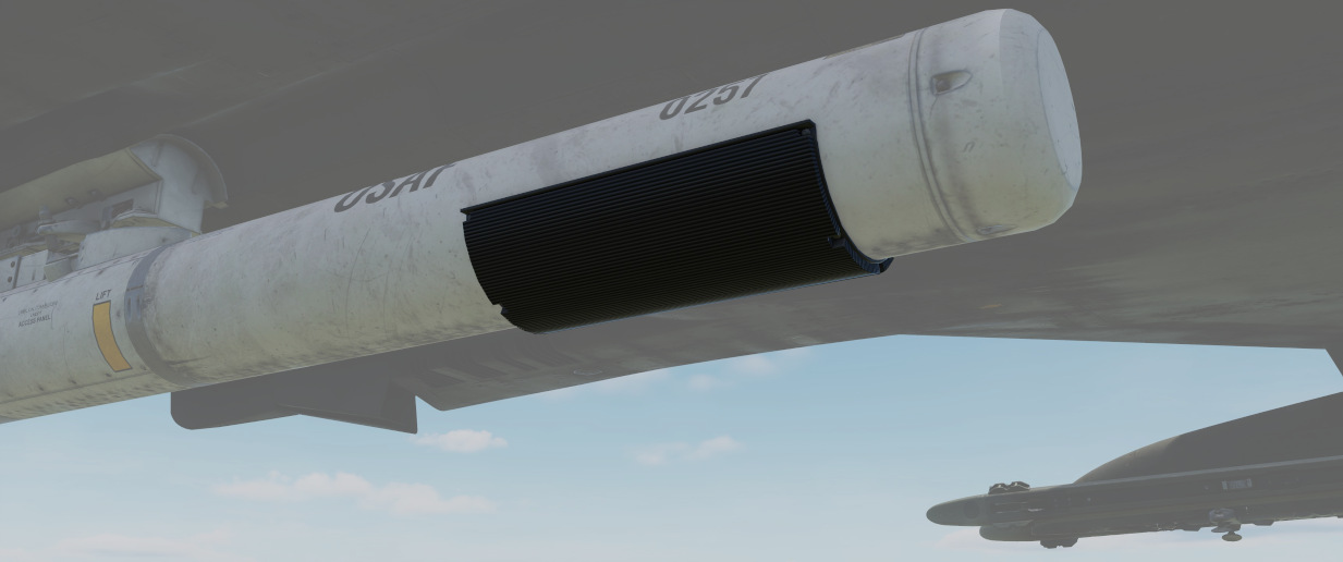
In general, the system is capable of keeping the pods temperature within limits during all normal operation.
However, if the temperature gets out of control, the Overheat lamp will illuminate.
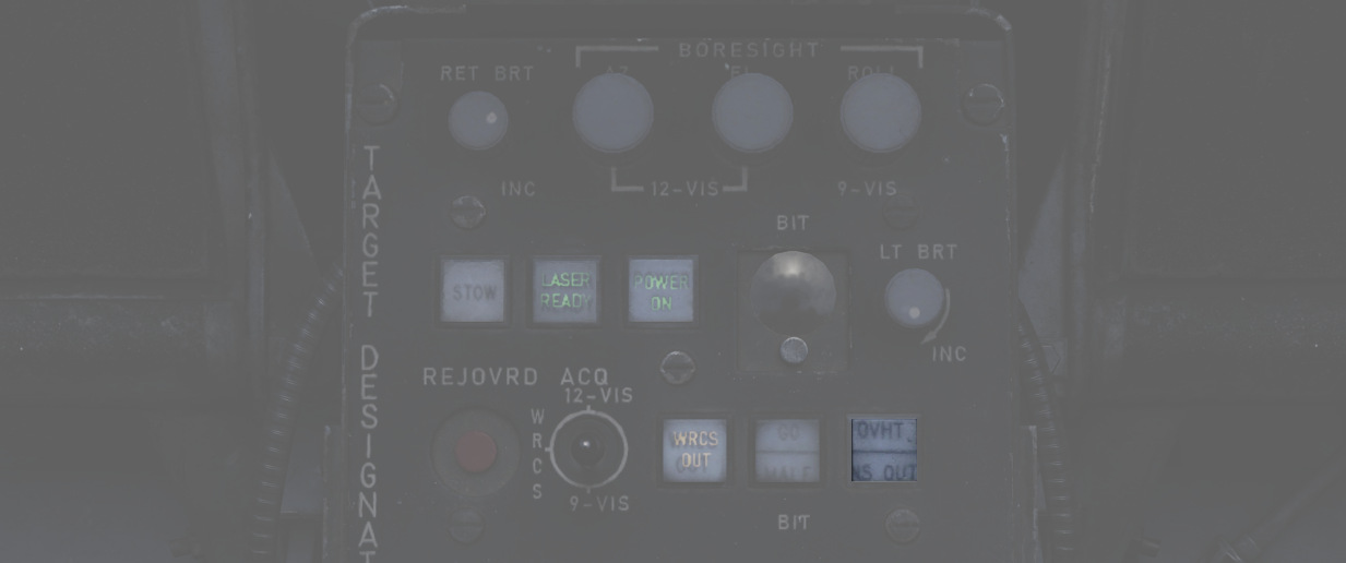
In this case, make sure to turn off the pod immediately and give it some time to cool down first. Ignoring the lamp will cause parts of the pod to melt, damaging it irreparably.
A broken pod is generally indicated by the MALF lamp going on and the display being all black.
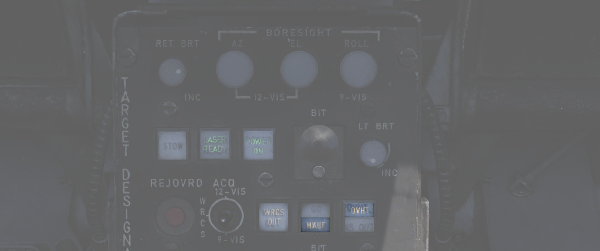
To prolong use of the pod and prevent overheating, limit slow and low-level flight, as well as continuous use of the laser.
🟡 CAUTION: As a rule-of-thumb, do not use the laser for longer than 15 minutes without allowing for cooling between uses. Limit continued slow and low level flight while operating the pod to 30 minutes. For extreme outside temperatures, adjust the limits accordingly.
Boresight
Normally the Pave Spike is correctly calibrated by the ground crew before getting into the plane, but it can drift due to combat damage or high G maneuvers in which case an in-flight recalibration by the WSO may be necessary.
Therefore, the Target Designator Control panel provides three knobs to adjust the boresight position in all three axis (azimuth, elevation and roll) within 2.5 degrees in either direction.
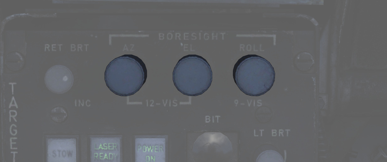
Under perfect conditions, the pod is boresighted parallel to the aircraft datum line. However, due to lack of a calibration reference, the WSO can only achieve a rough alignment.
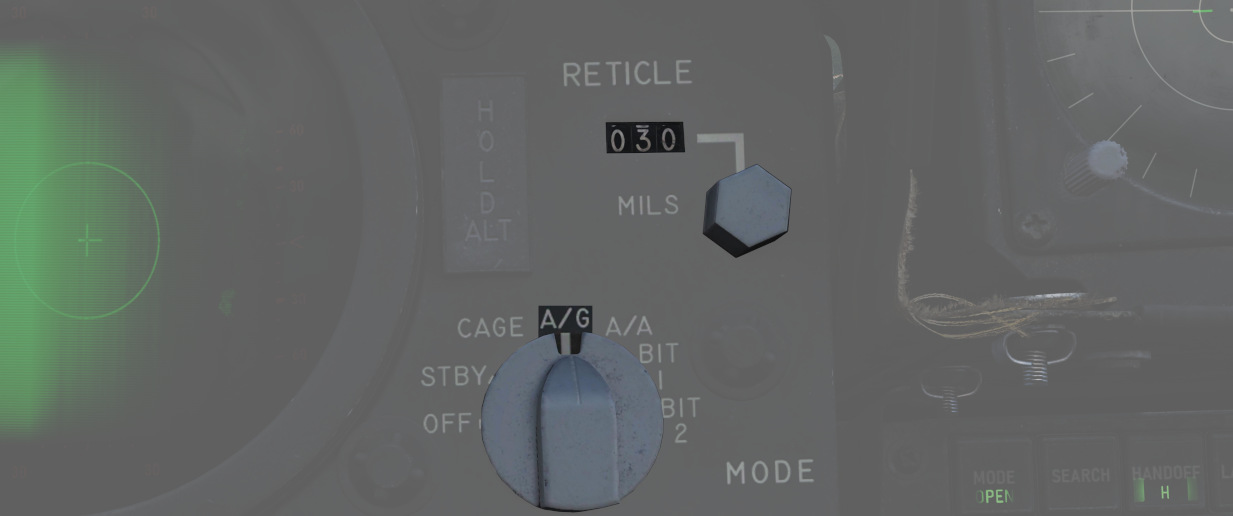
As first step, the optical sight should be put into A/G mode and the reticle must be depressed by around 30 mils. At this setting, the correct boresight position intersects with the sight reticle at a distance of roughly 20,000 ft to 60,000 ft (200 to 600 indicated on the Range Display).
 Next, the aircraft has to be maneuvered to place and hold a distant object, such as a building,
on the pipper of the optical sight.
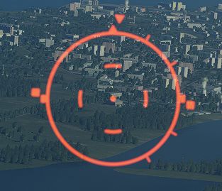
As the pilot holds the object on the pipper, the WSO must put the pod into the 12-VIS acquisition mode, activate the narrow field of view and can adjust the azimuth and elevation to align the pod with the object.
💡 Since the pod is loaded on the left station, the correct boresight position is offset a few feet to the left of the pipper.
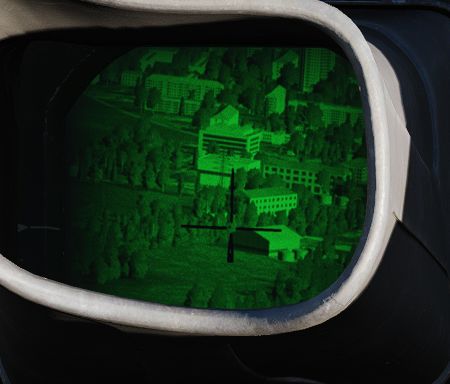
Roll is very difficult to align in-flight; if possible, land first. Then, place the acquisition switch into 9-VIS and use the Roll Knob to align the pod roughly with the height of a person standing in the distance.
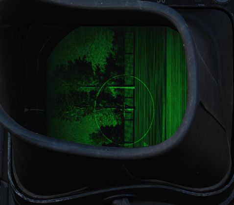
Alternatively, a rough roll alignment can be achieved in-flight by placing the acquisition switch into WRCS, integrating WRCS with the pod, and erasing any current target input. This way, the pod will automatically look straight down.
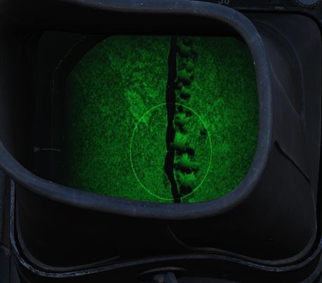
The aircraft can now be flown directly above a landmark, such as a river and the Roll Knob can be used to align the line of sight with the landmark.
BITs
The pod has 5 built-in tests, with BIT 1 being the actual mode used during normal operation. They can be activated and switched through by clicking the BIT button below the display. The GO/MALF lights show the result of the BIT:
- GO - test was successful
- MALF - test detected a failure
During normal operation, activated through BIT 1, neither of the lights are illuminated.
BIT 0
All lights on the Target Designator Set Control illuminate with full brightness. The pod does not need to be powered up for this test.
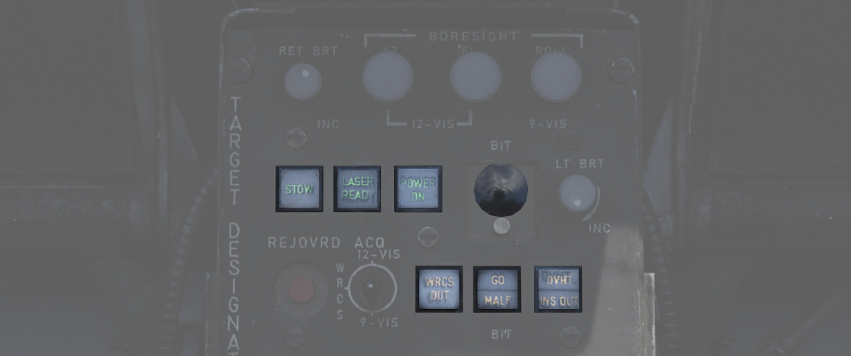
GO/MALF do not indicate test results in this mode.
BIT 1
The circuits are energized and monitored. If any voltage reading is abnormal, MALF illuminates.
GO does not illuminate in this mode.
This is the standard operational mode. The pod can be used normally and the system will continuously monitor the status.
BIT 2
The system simulates track functionality, simulating all inputs, altitude and range data.
After about 15 seconds, the test is finished with either GO or MALF illuminating.
💡 For the test to be successful, the aircraft must not be moving, the pod must be un-stowed and INS must be integrated.
Bit 3
This tests the laser energy level. The pod moves to a special position where it looks inside itself, such that the laser fires against a special sensor mounted inside the pod.
The pod must be un-stowed and a valid laser code must have been entered, as well as the LASER READY button being pushed in. The nose gear guard is ignored during the test, allowing the use of the laser on ground.
Once the pod has reached the test position, the WSO must press and hold the Reject/Override button to start firing the laser. The laser stops firing when the button is released.
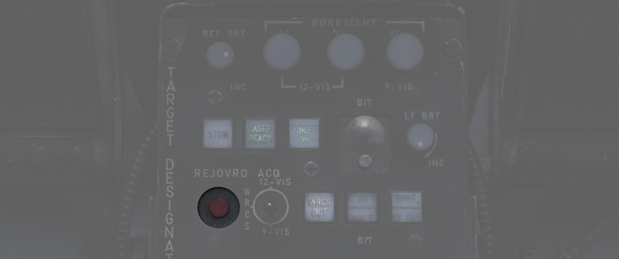
When the laser fires, a 5 second test program starts, with the sensor measuring the laser energy. After the 5 second test, either GO or MALF illuminate to indicate whether the energy level was above the required minimum.
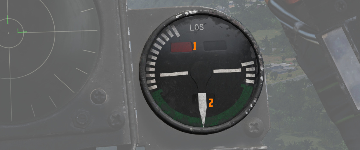
The pilot can assist in telling the WSO that the test position has been reached, as indicated by the Azimuth-Elevation Indicator (1 and 2).
Bit 4
The system tests the ranging computation by feeding a simulated laser slant range of 2100 ft (±200). The pilot can confirm this using the Range Indicator readout.
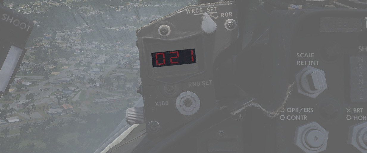
After about 8 to 14 seconds, the test is finished and either GO or MALF is lit.
Upgrades
Based on crew feedback, the Pave Spike targeting pod received two major upgrades, which are available as separate selectable weapon in DCS.
Smart-Track
TCTO 518, known as the Smart-Track upgrade, aims at removing the requirement to press the Reject/Override button to force the laser measured slant range in situations in which the computed slant range was usually too inaccurate.

With the upgrade, the system will automatically accept the laser slant range whenever the pods elevation gimbal is above -7.5 degrees. I.e. in shallow angles, for example during 12-VIS mode or low altitude attacks.
Fast-Track
The popular upgrade TCTO 519 overhauls the pods gimbal motors, increasing the movement speed from 15 dps to 60 dps.
💡 At this speed, the targeting pod is capable of tracking a target during low altitude high speed flight, such as overflights at 1,000 ft with 500 knots.