Weapon Release Computer Set (WRCS)

Provision for the F-4E to perform accurate level and dive munition delivery is provided by the AN/ASQ-91 WRCS. The WRCS inputs are set with the associated panels in the cockpits, and these commands, along with INS data and radar target ranging, are used by the ballistic computer to provide the release signal.

Target Range Controls
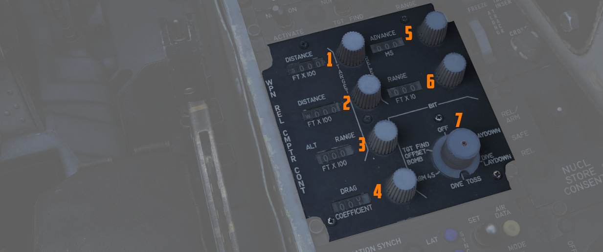
The Computer Control Panel found in the rear cockpit has three TARGET entry controls, two RELEASE entries, and a bomb DRAG COEFFICIENT entry setting, as well as a BIT control knob for system function check. Target entry is relative to the predetermined IP.
The upper range control input is for North/South, and selection of relative bearing is noted by the N or S prefix at the start.
The middle range control input is for East/West, and like the previous, the E or W prefix on the range sets the relative bearing direction.
The final ALT RANGE entry is for target altitude- whether the target or RIP (Radar Identification Point) elevation as MSL, or the target/RIP's pressure altitude. In Laydown mode the entry refers to the distance between the IP and the target in hundreds of feet.
Entries for North/South and East/West are in 100 foot increments, and a maximum value of up to 99,900 feet may be entered for these distances. The ALT RANGE entry has a maximum of 24,900 in 100 foot increments.
💡 The WRCS can be damaged if the ALT RANGE entry is greater than the aircraft's current MSL (x100) in TGT FIND and OFFSET BOMB modes.
Release Range Control
The Release Range control is used to manually set bomb range in tens of feet, and is accessible in the Laydown, Dive Laydown, and Offset Bombing modes. The maximum setting is 9990 feet (999x10), and when used in a WRCS/AJB-7 integrated delivery, the actual range can be as high as 99,900'.
The Rg control should not be set to the same value as the target range control. Otherwise, the bomb rack delay may release late, or not at all.
Release Advance Control
Operative in all WRCS and WRCS/LABS integrated motes, the Release Advance Control works in conjunction with the AWRU to advance the release signal in milliseconds. Whereas the AWRU Intervalometer setting triggers the release pulse sequence from the moment the bomb release button is pressed, when the Release Advance Control is applied in a WRCS driven delivery, the specific bomb location in a multiple ripple sequence can be calculated in advance, allowing the most effective spread possible across a given target.
As an example, an AWRU single-ripple quantity release of 4 is selected with an interval of 120 milliseconds. To place the third bomb in the ripple on target, the following equation is used:

where
RA= Release Advance Setting, millisecondsI_R= AWRU Release Intervalometer setting, millisecondsN_Tgt= Impact Sequence number of bomb desired on target

Thus, for this release, we would set the value of RA to 240 msec. This would produce a spread of two bombs ahead of target, one on the calculated target point, and one behind.
The maximum setting for the Release Advance Control is 999 milliseconds. A calculator to calculate the Release advance in-game is provided with the bombing calculator. You can open and close it by pressing RCTRL+B in game.
Drag Coefficient Control
Used only in the Dive Toss Mode, this entry is a bias factor prepared for the ballistic computer to compensate for actual bomb trajectory. The maximum setting for this value is 9.99.
Ballistic Computer
The ballistic computer is not directly accessed by the flight crew, but instead pre-set based on the configured loadout by the ground crew to add the necessary ejection bias factors. The computer uses these pre-set bias factors in conjunction with a coefficient setting for munition drag in the Dive Toss mode to calculate accurate delivery.
WRCS Built-In-Test (BIT)
The BIT control is used to confirm go/no-go status of the WRCS. The BIT system checks individual bomb modes individually, and effectivity of the given setting is confirmed by selecting the desired mode, pushing the center of the knob PUSH FOR BIT for five seconds, then pressing the FREEZE button in conjunction with the PUSH FOR BIT button. Confirmation of mode performance will be displayed as GO or NO-GO. Should a mode be checked a subsequent time during a flight and a NO-GO response is received, it can be disregarded.
Cursor Control Panel

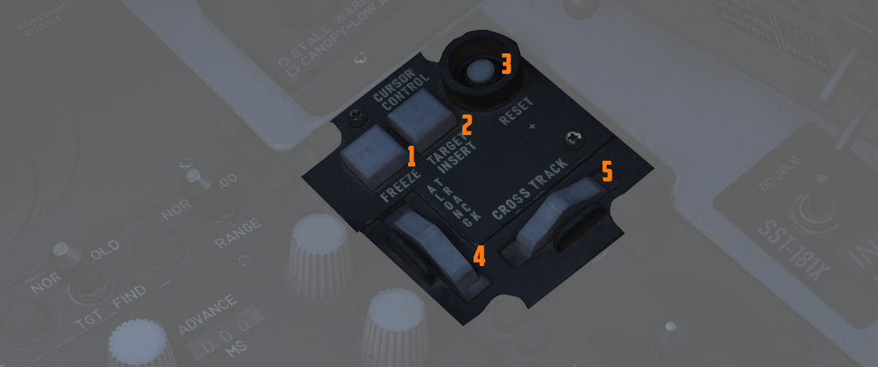
The Cursor Control Panel provides the controls needed for TARGET FIND and OFFSET bombing modes. The panel has two wheels named ALONG TRACK and CROSS TRACK, which is used in the MAP-PPI mode to position their respective cursors over the Radar Identification Point (from this point denoted as RIP). The ALONG TRACK control, which presents relative range to the RIP, also includes an internal switch enabling the cursor instructions to be acknowledged by the WRCS ballistic computer, and must therefore be the first applied command in the target insertion sequence.
Once the ALONG TRACK (range hemisphere) and CROSS TRACK (vertical line) cursors are aligned over the RIP, the FREEZE button is pressed to initiate WRCS ground path tracking of the specified point. The button remains illuminated until the RESET button is pressed or another bombing mode is selected.
With WRCS ground tracking initiated, the TARGET INSERT button is pressed for the ALONG TRACK and CROSS TRACK cursors to shift from the RIP to the offset target. Once selected, target steering information is provided from the WRCS to the BDHI, ADI, HSI, and optical sight. In the AGM-45 missile mode, the AoA Indexers will provide maneuver commands for level, dive, or climb requirements to align for seeker acquisition. Further, unless the Pull up tone switch is disabled on the LABS panel, an audio tone will be triggered from the point of bomb release button press until the first bomb releases from the aircraft; this function is nominally for training purposes, as it can preclude other system audio volume.
Weapon Delivery Panel

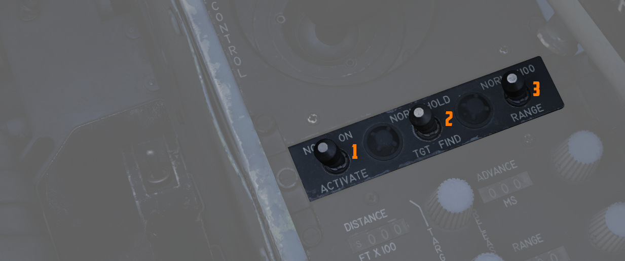
The Weapon Delivery Panel permits the aircrew to use the WRCS TGT FIND functions in LABS (ARBCS) modes - those found on the left side of the pilot's Delivery Mode Knob.
The TGT FIND switch on the panel functions the same as the TGT FIND mode on the Delivery Mode Knob. The Delivery Mode Knob overrides this switch in any mode outside of TGT FIND, and should be set back to NORM. The HOLD position energizes the target finding circuits in conjunction with any LABS or DIRECT mode the pilot selects.
The RANGE Switch is functional in any WRCS mode requiring a Release Range setting. The NORM position applies the noted x10 multiplier on the displayed Release setting, whereas selecting x100 applies a multiplier of 100 to the counter value.
The ACTIVATE Switch triggers the prerequisite activation signals to the LABS circuits once the aircraft has passed within the Release Range. The switch should only be placed in ON after target insert has been pressed and the ALONG TRACK and CROSS TRACK cursors have transitioned to the target.