Right Wall
The right wall has auxiliary switches for testing and starting the aircraft.
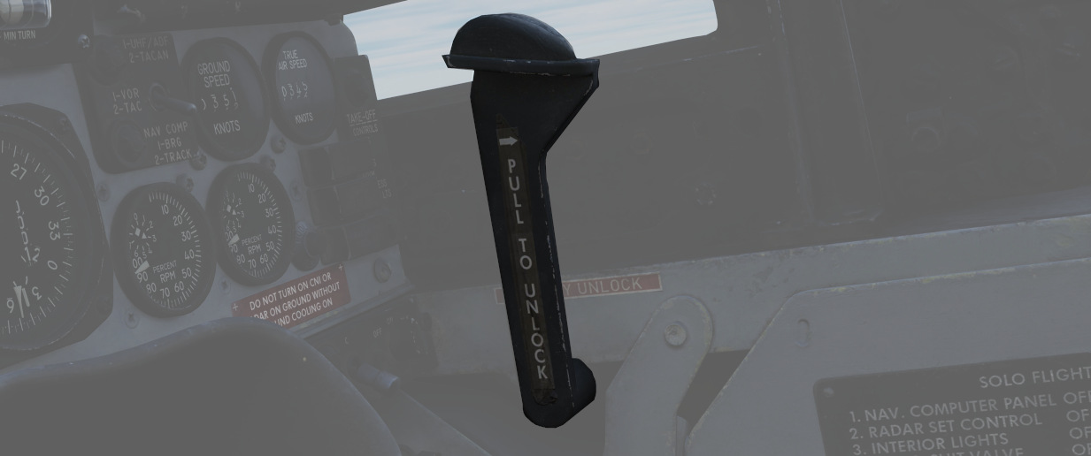
Canopy Manual Unlock Handle

The manual unlock handle is used in the event of pneumatic system failure.
The handle, when pulled aft, unlocks the canopy so that it may be pushed open. Before manual unlocking of the canopy, the normal control lever must be placed in the OPEN position.
For normal operation, the handle should be left in the forward position.
If the canopy is not properly locked, the CANOPY UNLOCKED warning light on the telelight panel illuminates.
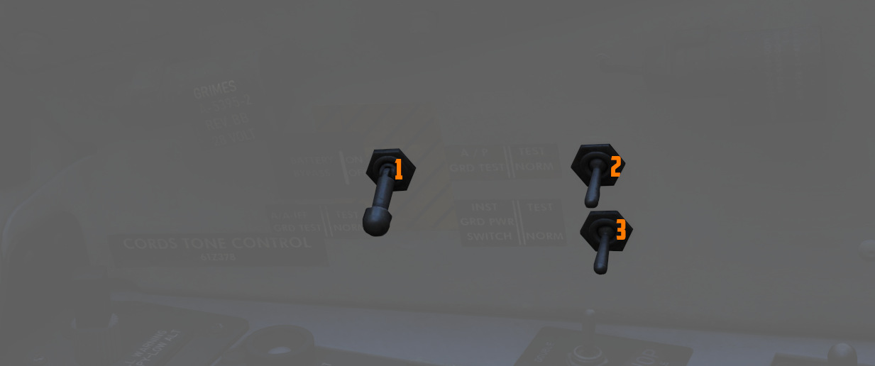
Ground Test Panel

Battery Bypass
When toggled ON (
Autopilot Ground Test
The autopilot ground test switch (
Instrument Ground Power
In the TEST position (
This can be used during a cold-start after applying ground power and before starting the engines, to already setup the aircraft and operate some systems that require power on these buses.