Aft Section
The aft section of the right console features the navigation and lighting panel.
Navigation Panel
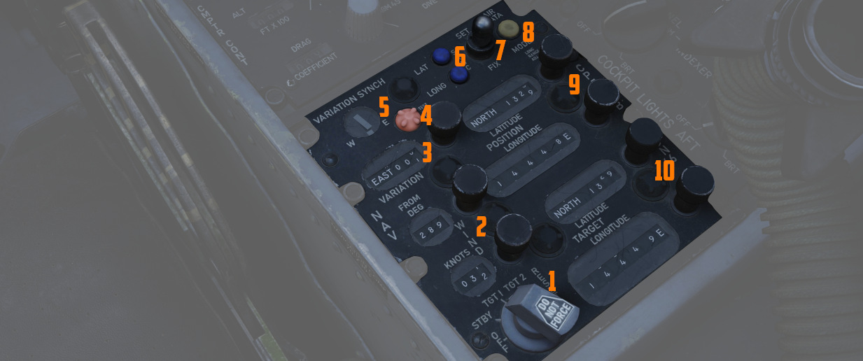
The Navigation Computer Control Panel serves as an interface for managing the aircraft's navigation, including its position and targets for navigation instruments like the HSI and BDHI. It can operate in two modes: INERTIAL and AIR DATA.
See Navigation Computer for details.
The panel is equipped with a range of control knobs and switches essential for the operation of the Navigation Computer.
Function Selector Knob
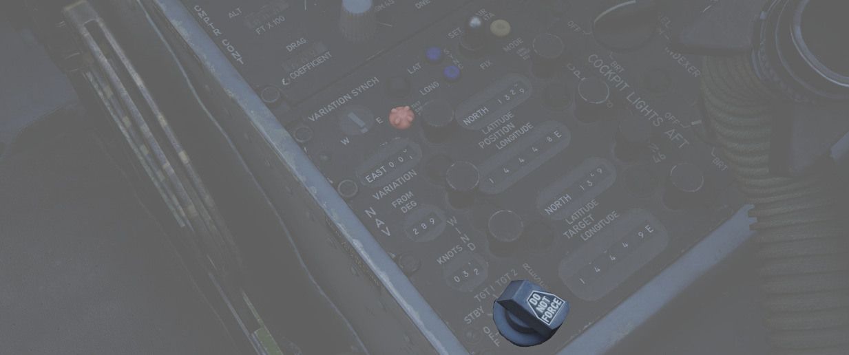
A five position rotary switch (
| Position | Description |
|---|---|
| OFF | System powered down. |
| STBY | System is powered but the latitude and longitude position integration is off. |
| TARGET 1 | Computes range and bearing to the selected coordinates set on the TARGET rollers. |
| TARGET 2 | Computes range and bearing to the memorized coordinates. |
| RESET | Clears the memorized coordinates. When moved back to TARGET 2, the selected coordinates set on the TARGET rollers are memorized. |
Wind Control Knobs and Counters
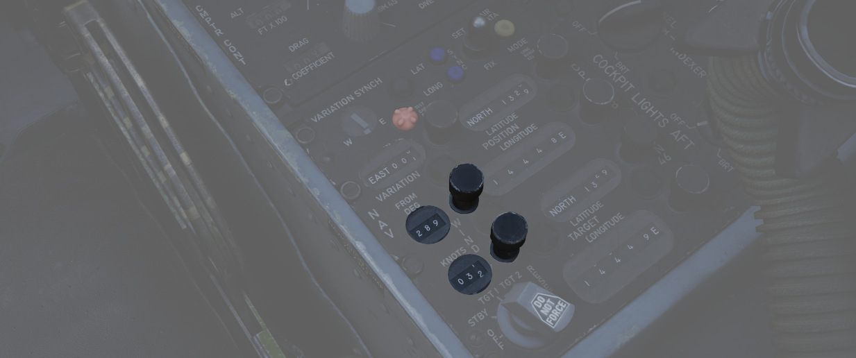
Two rotary knobs (
Magnetic Variation Knob and Counters
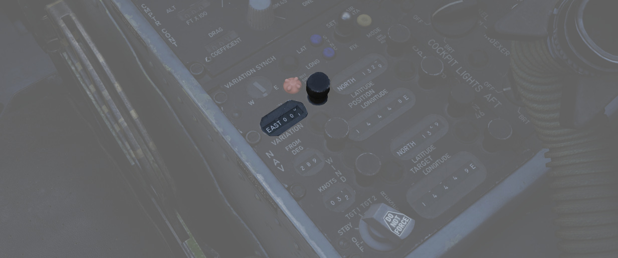
A rotary knob (
Position Control Knobs and Counters
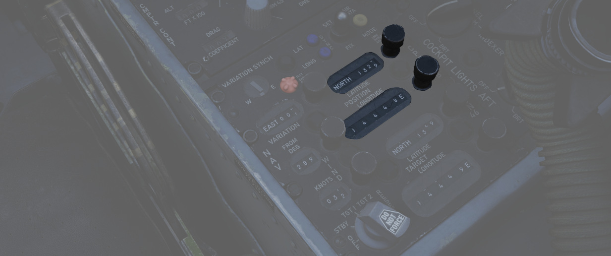
These knobs (
💡 In INERTIAL mode, the Position Update Switch must be used in conjunction with these knobs to update the position coordinates.
Target Control Knobs and Counters
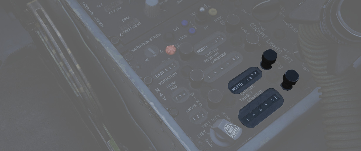
The target controls (
Position Update Switch
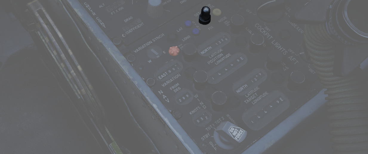
A three position switch (
| Position | Description |
|---|---|
| SET | Disengages the updating mechanism of position counters, allowing them to be freely rotated to the desired position. |
| NORMAL | Position counters are updated based on the INS signal in Inertial Mode, or by the system's own computations in Air Data Mode. |
| FIX | Updates the INS position at a rate of approximately 3 minutes of arc per second. |
💡 The switch features an approximate 0.5-second delay when set to NORM, designed to prevent unwanted updates of the counters during the transition from SET to FIX.
Variation Sync Meter
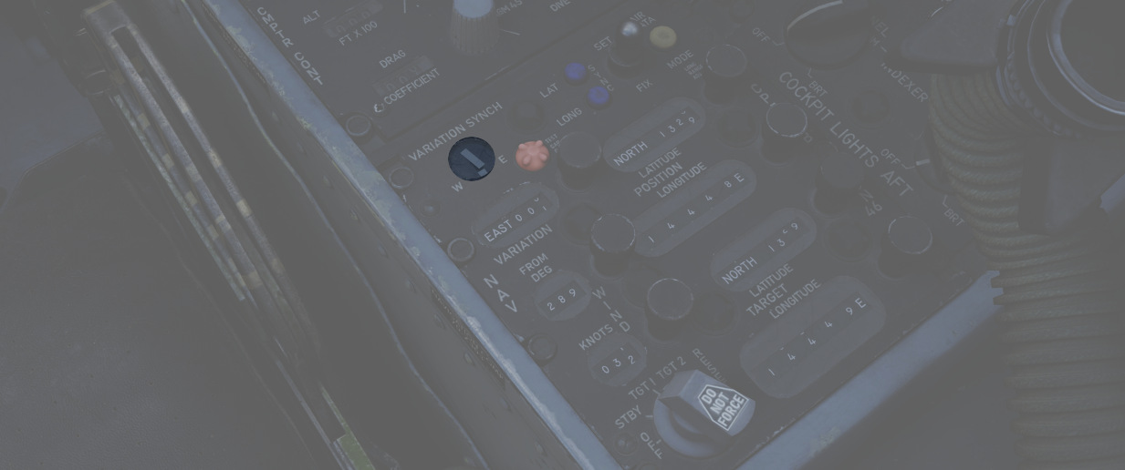
In Inertial mode, this meter (
Test Cap Off Light
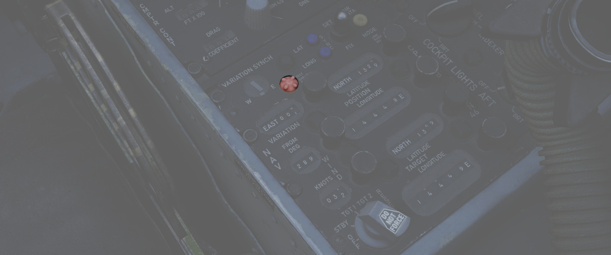
Illuminates (
Latitude and Longitude Sync Lights
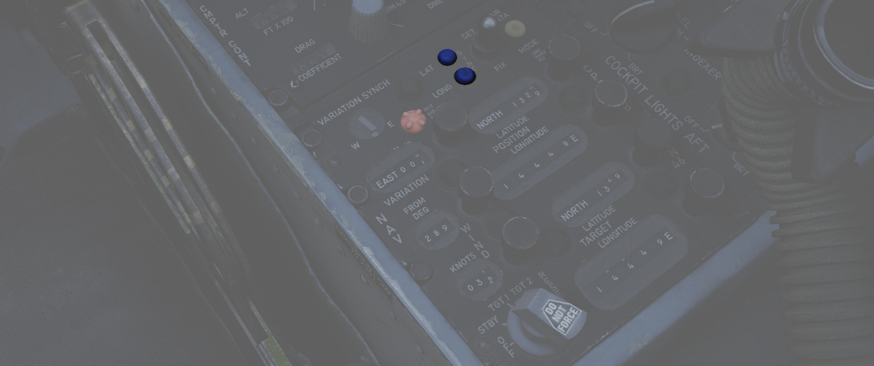
Illuminate (
Air Data Mode Light
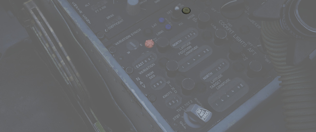
Illumination (
Cockpit Lighting Control Panel
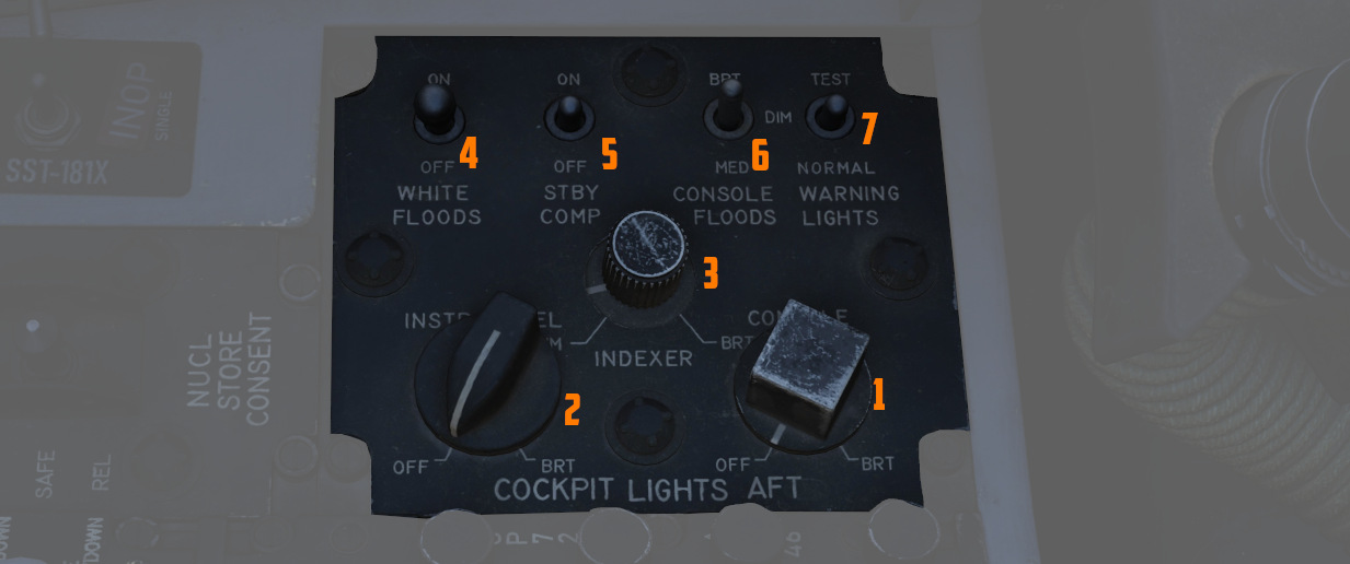
The Cockpit Lighting Control Panel provides control of all panel edge lighting, flight instrument panel lighting, the console floodlights, the white floodlights found under the canopy sill over each console, and also includes the Warning Light Test and Standby Compass Light switch.
White Floodlight
The White Floodlight switch (
Standby Compass Switch
The STBY COMP switch (
Console Floodlight
This switch (
💡 To turn them off, place the switch in DIM and the Console Knob in OFF.
💡 Floodlights for the Instrument Panel are controlled by the pilot, see the Instrument Flood Switch.
Warning Light Test Switch
The Warning Light Test Switch (
Instrument Panel Knob
This knob (
💡 The main flight instruments are controlled by the pilot via the Flight Instrument Brightness Knob instead.
Indexer Knob
Controls the brightness (
Console Knob
The Console Light Control Knob (