AN/ASN-63 Inertial Navigation System
The AN/ASN-63 INS provides the F-4E aircrew and integrated weapons delivery system with real time accurate positional, velocity, attitude, and heading information. When the system is aligned to its most precise extent in gyrocompass mode, the INS is accurate to 3 nautical miles per hour of circular error probability (CEP).
💡 That means that after one hour of flying, the probability for an error in precision is spread such that in 50% of cases it is either below or above 3nm.
Inertial Measurement Platform
The system uses a four gimbal (outer roll, pitch, inner roll, azimuth) inertial navigating platform, with the dual roll gimbals providing redundancy to eliminate a gimbal lock in outer roll/azimuth gimbal alignment.
Installed on the platform are a pair of G-200 two-axis gyros, with the upper gyro axis aligned for spin on the north-south axis while the lower gyro aligns for east-west spin; torque detection in each gyro tracks the perpendicular axes - ergo, the high gyro detects east/west rotation, while the low gyro detects north/south rotation. In this way, rotation in all three dimensions are represented. The gyros are floated, and proper operation can only take place once the fluid has attained operating temperature (160 degrees F); the system is effectively temperature controlled across the altitude operating range of the Phantom. A series of precision magnetic torquers provide localization movement, while acceleration pick-offs function within a separate electromagnetic field perform the actual data capture from the displacements of the gyroscopes.
Along the platform, set orthogonally (at 90 degree respective positions) are a trio of A-200D accelerometers. These accelerators, similarly floated to the gyros, with a similar arrangement of torquers and displacement pickers to provide velocity capture. Increasing the accuracy of these evaluations is the inclusion of a tuning fork, the resonance from which eliminates effectively all static friction in the motion capture assembly.
Navigational Computer and Output Signal Distribution
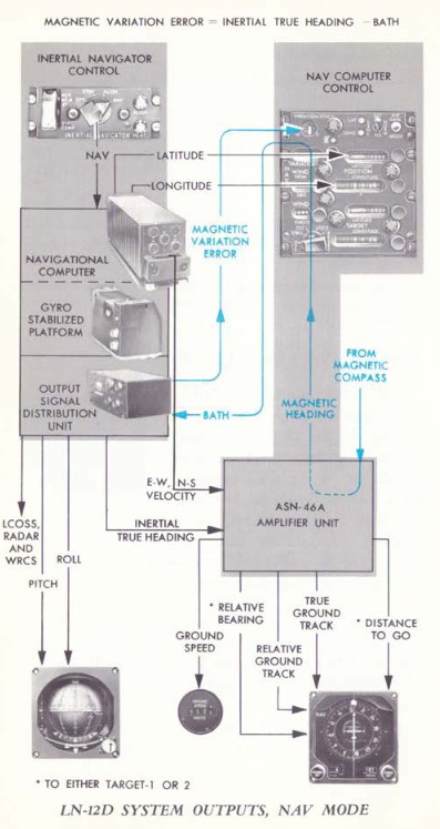
The respective captured motion signals from the gyroscopes and accelerometers are amplified in the LN-12D navigational computer, which then performs the earth reference integration. The LN-12D compensates for all longitudes and can effectively track as high as 80 degrees latitude, where the mechanical limitations of calculating tangent relative to the equator is too high for the device.
The AN/ASN-63 provides information to other systems in the Phantom from the OSDU, or Output Signal Distribution Unit. The OSDU provides ground speed, north-south and east-west velocity, total velocity, inertially stabilized altitude, climb angle, true inertial heading, ground track, and drift angle. The WRCS receives inertial true heading, ground track, drift correction angle, and drift angle for its ballistics computer. Drift angle is captured for the BDHI, HSI, and FDC. Drift correction angle is also provided to the radar and LCOSS.
Alignment Options
The LN-12 has three modes of alignment on aircraft start: BATH, Heading Memory (HDG MEM), and Gyrocompass alignment. Prior to performing any alignment, STBY Reference System must be selected, the Nav Computer Control Panel should be turned to STBY and its position update switch should be selected to NORMAL. Local magnetic variation should be entered on the variation counter, and the position counter should be set to local latitude and longitude. Doing so will greatly expedite gyrocompass alignment. Furthermore, alignment should not be performed with the wings in their folded position, as the magnetic flux valve that provides compass synchronization wil be 60 degrees outside of normal position.
The INS also includes an in-flight position update option, should the aircrew note gross deviation from known location fixes.
Indications
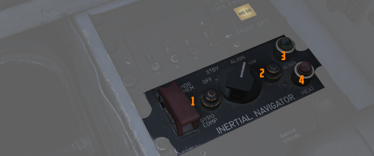
The INS panel features two indicator lights: HEAT (
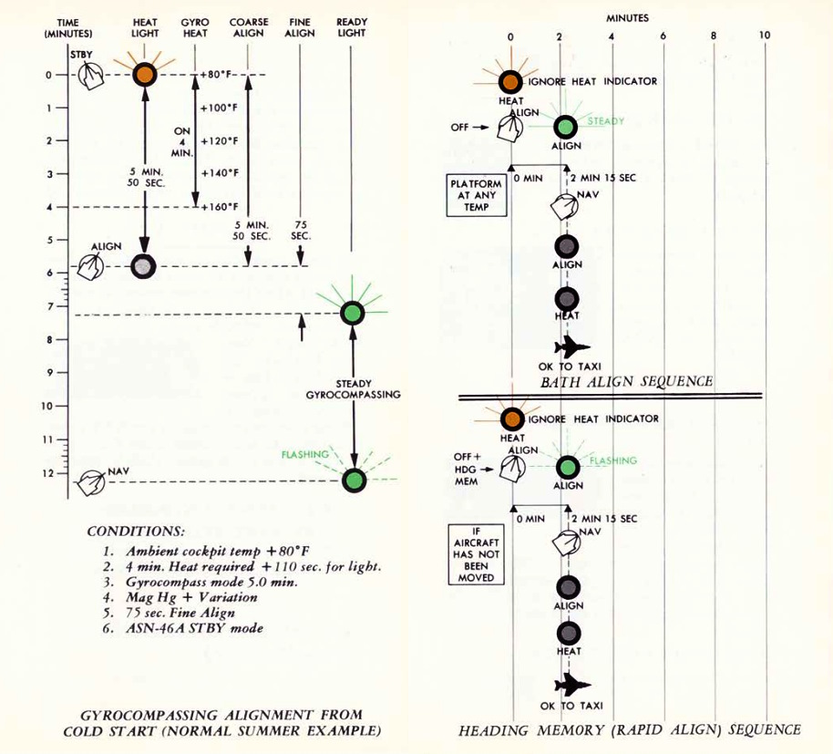
The HEAT light is active in any alignment mode (including Coarse Alignment in the STBY mode), signifying that the system is heating up. It turns off after approximately 110 seconds, indicating that the gyros have reached the operational temperature of 160 degrees Fahrenheit.
The ALIGN light, functional exclusively in the ALIGN mode, signals the completion of alignment. A steady ALIGN light indicates that a BATH (fast) alignment has been achieved. Provided the system has not encountered any errors and the gyros were pre-heated in STBY mode (evidenced by the extinguished HEAT light), the system will proceed to perform a Gyrocompass Alignment. A flashing ALIGN light signifies the completion of either a Gyrocompass Alignment or a Heading Memory Alignment.
Best Available True Heading
STBY position must be placed momentarily to avoid an INS no-go. Once set to ALIGN (HEAT light may be ingnored), the ALIGN lamp will illuminate steadily after about 75 seconds indicating BATH Alignment is ready. Once in BATH, the INS is accurate to roughly 5 and a half nautical miles per hour CEP, although higher inaccuracies can be seen. Once BATH is achieved, NAV mode can be selected and the aircraft flown with the above caveat.
Heading Memory Alignment
This option becomes accessible if the alignment has been previously stored and
the aircraft has remained stationary. To access it, select HDG MEM (
To access the accelerated HDG MEM alignment mode, the guard must be raised and the switch actuated up, and the INS mode switch placed to ALIGN until the ALIGN lamp starts flashing. Then, the INS can be placed into NAV mode. If time allows, STBY mode can be selected before going to ALIGN to allow proper heating of the gyroscopes (which goes through the illumination/off cycle as above).
💡 Heading can be stored in the mission editor.
Gyrocompass Alignment
Maximum system precision is found by allowing the INS to perform a full Gyro-compassing alignment. This method permits the gyros to find the most accurate true north reference possible, but can entail substantial amounts of time - and even greater time based on inaccurate or missing magnetic variation setting entry prior to powering the INS on. As an example - for a one degree compass heading error, the time to achieve maximum accuracy on the system is approximately five minutes, which attains an accuracy of ±10 minutes of arc alignment, giving the aforementioned 3 nautical miles of deviation per hour. The minimum amount of time to complete a Gyro-compassing alignment once BATH or HDG MEM level alignment is achieved is 50 additional seconds, while a normal alignment takes around 5 minutes. If the aircraft is aligned at 70 degrees of latitude or more, additional time should be expected.
To conduct Gyrocompass Alignment, it's necessary to keep the INS in STBY mode until the HEAT light turns off. Moving to ALIGN while the lights are still on prevents achieving full Gyrocompass Alignment, resulting in only the BATH process being performed. The duration of the heating phase depends on the ambient temperature. The system heats up at a rate of approximately 20°F per minute, reaching an operational temperature of 160°F. Once the system reaches its operating temperature, an additional 50 seconds are required until the HEAT light extinguishes. After transitioning to ALIGN, the light will illuminate steadily after 75 seconds, signaling the completion of the initial BATH alignment, initiating the gyro-compassing process. Once Gyrocompass alignment concludes, the ALIGN indicator will flash, indicating the system has achieved full alignment. While gyro-compassing (when the align light is steadily lit), NAV mode can be entered at any time, though optimal accuracy will only be attained when the ALIGN indicator flashes.
Any other available time prior to moving the aircraft can be spent in ALIGN to further increase system accuracy.
In-Flight Emergency Alignment
In the event of a significant attitude error or failure of the STBY Attitude Reference, an emergency in-flight alignment of the INS can be executed. This may be indicated by the NAV SYS OUT LAMP illuminated. The aircraft must maintain straight and level flight, with the Reference System Selector selector switch set to STBY. Once in this configuration, the INS Mode Knob should be switched to OFF, then to STBY for a duration of 15 seconds. Subsequently, after the 15-second interval, return the Mode to NAV, and resume straight and level flight. The process of resetting the Reference Selector to PRIM can be performed approximately after 40 seconds, although the precise alignment time is not specified.
💡 Accuracy of the attitude in this alignment is contingent upon how steadily the aircraft was flown during the alignment period and subsequent alignments may be required. Following this emergency alignment, only attitude information will be available. Velocities, position, and displays on the navigation computer will be inaccurate and cannot be utilized for navigation purposes and the NAV SYS OUT LAMP will illuminate.
Navigation Computer
The ASN-46A Nav Computer is used for general navigation and tactical route planning. The system contains both a great circle and rhumb line computational capabilities, with the former being used for larger distance bearing calculations (over 120 miles), and the latter for closer range accuracy. The Nav Computer functions solely using aircraft-based instruments, ergo the INS, Air Data Computer, and the magnetic compass; it can receive no information from the ILS, VOR, or TACAN systems.
The system can maintain relative bearing and distance from up to two specific waypoints at a time (identified as Target 1 and Target 2, with Target 2 being held in memory), and this information is shown on the BDHI and ADI in real time. For data to appear on the BDHI, the Navigation Selection Switch must be positioned in NAV COMP.
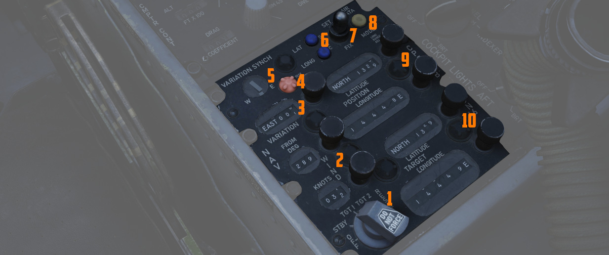
The computer also provides confirmation of current LN-12 precision, using a pair
of lights (
The Nav Computer can function in either Inertial or Air Data mode. Both modes provide the same outputs but the inertial mode (default) is more accurate.
In the event of an INS failure, the Nav Computer reverts to Air Data mode. In Air Data mode, the rear pilot must continually monitor and adjust true wind direction and speed, magnetic variation, as the only dead reckoning inputs available to the computer is true airspeed (from the air data computer) and magnetic heading from the compass system. When the system reverts to Air Data mode, the AIR DATA MODE lamp will illuminate.
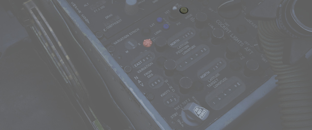
During startup, the Position Control Knobs, Wind Control Knobs, and Magnetic Variation Control Knob are used to enter known latitude, longitude, wind direction and speed, and magnetic variation for the location of the aircraft at that time.
Waypoint Entry
Entering waypoints and target information is performed using the Function
Selector Knob and the two Target Control Knobs (
| Name | Description |
|---|---|
| OFF | System off. |
| STBY | System powered, but no latitude or longitude reference performed versus the values in the Target windows. |
| TARGET 1 | Provides readouts of range and bearing on the currently entered Target window values. |
| TARGET 2 | Selects range and bearing information from previously stored Target window values. |
| RESET | Deletes any previously saved Target window values, stores currently entered Target window values. |
Because of the Target 2 memory function, in practice the aircrew has some flexibility in process depending on the demands of the mission. As an example, should the Phantom crew be tasked with a CAP or defensive role relative to a known position (ie, bullseye), the coordinates of that location can be loaded into the Target Control values, the Function Selector placed into RESET, and then returned to Target 2. Any change from Target 2 to Target 1 or STBY, then back to Target 2 will maintain said location value, easily accessed. This will memorize the entered position into Target 2, from which it will be easily accessible by just switching the knob back to Target 2 at any time.
The other common technique was "leapfrogging":
-
On startup, the second waypoint would be stored in Target 2 memory (entry on the Target Control values, Function to RESET, then back to Target 2).
-
Once the second waypoint location was stored, the rear pilot would then select Target 1 for live entry of the first in-flight waypoint on the Target Control values.
-
During flyout to the first waypoint, upon passing it over, Target 2 would be selected as the destination, and the next waypoint (
3 ) would be entered on the Target Control Values. -
Upon flyover of waypoint 2, the Function Knob would be positioned to RESET, then back to Target 2 - now pulling the waypoint 3 values from the Target Control values.
This process would be continued over the course of the flight, and allow the rear pilot the ability to immediately switch to Target 1 for a quick check of relative position to another location of interest if required, or an in-flight detour (such as to a tanker track), then return back to the next stored waypoint for navigation.
In Flight Updating
In flight updating with the Nav Computer is performed using direct overflight of known target points, using a visual or radar fix, over a TACAN station, or via instruction from GCI.
Inertial Mode Update
With the Nav Computer in Inertial mode, the aircraft is flown straight and level at a known fix location.
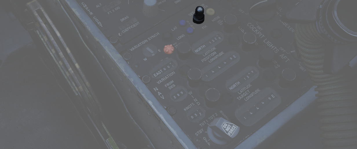
-
Prior to arrival at the fix point the Position Update Fix is placed in SET position. Doing so disengages the longitude and latitude position counters.
-
The position longitude and latitude counters are set using their respective knobs for the known location.
-
Directly before overflying the fix point the Position Update Switch is placed and held in the FIX position.
-
Upon direct flyover of the fix point, the Position Update Switch is released, allowing it to fall back into NORMAL.
The correction rate of the Nav Computer is roughly 3 minutes latitude or
longitude per second, and the Update Switch (
Air Data Mode Update
In Air Data Mode, the Nav Computer can be updated as in the Inertial Mode using the SET/FIX method, or via direct rotation of the latitude and longitude position knobs. Using the latter method requires the Function Select Knob to be placed in STBY, TARGET 1, or TARGET 2. The SET/FIX method is preferred, as doing so allows for instant update upon fix position flyover and release of the switch.