Upfront Indicators
The front of the canopy provides the WSO with all relevant flight instruments and gauges.
Standby Magnetic Compass
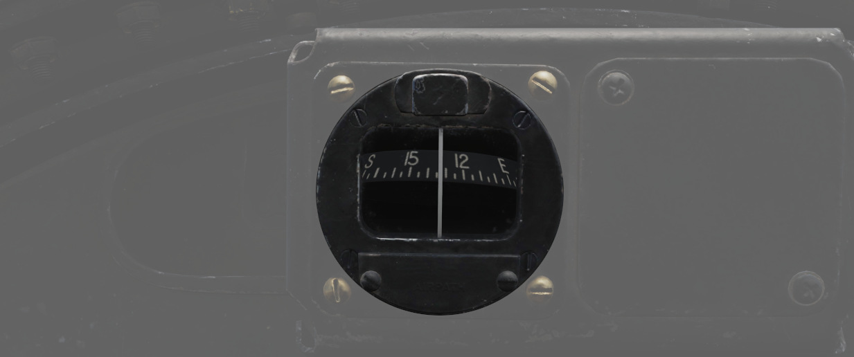
A standard magnetic compass for backup navigation assistance should the primary flight director systems fail.
The compass should only be used in level flight. Compass deviation cards are found above the right canopy sill on each cockpit.
Command Ejection Select Handle
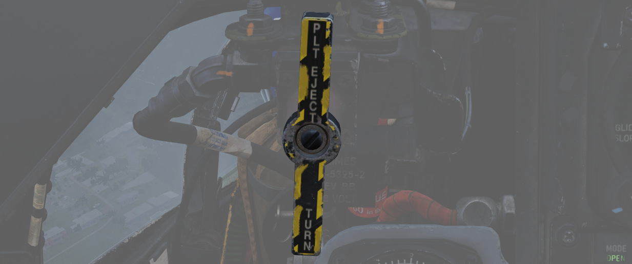
Used to select single or dual ejection as commanded by the WSO. In the vertical position (valve closed), initiation of ejection by the WSO ejects only the rear seat. With the valve handle in the horizontal (open) position, a WSO initiating ejection will extract both crew members.
Course Indicator
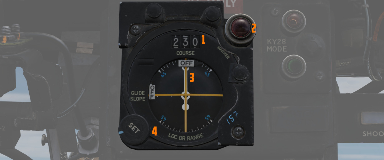
Used during an ILS approach, displays localizer and glide slope
deviations represented dots (
The heading pointer (
Does not function with TACAN or VOR. OFF flags display on signal loss.
Marker Beacon Lamp
The lamp on the top right (
The lamp can be rotated to dim and pushed to test.
See VOR/ILS System for details.
KY-28 Mode Indicator
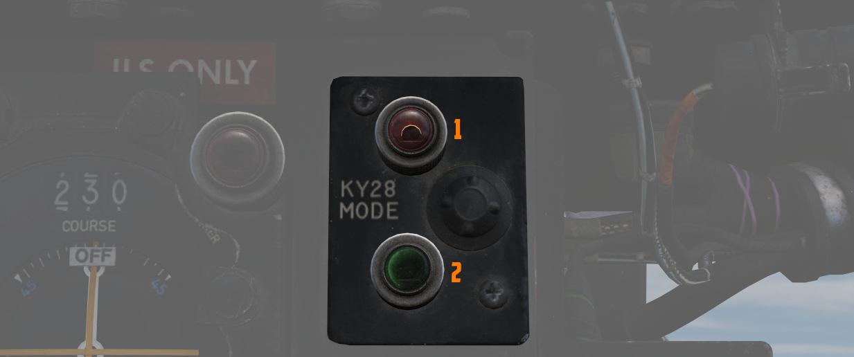
Two lamp indicator illustrating current KY-28 operating mode- P (
💡 UHF communications require the system to be in Plain mode, even with the system power off, barring usage and monitoring of the guard channel.
Master Caution Light
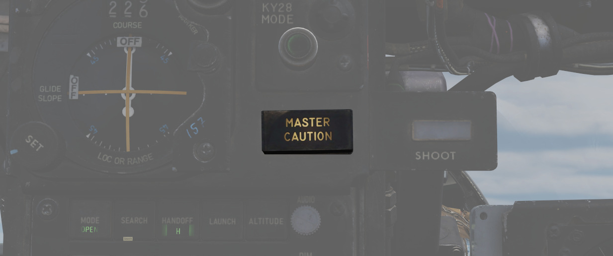
A repeater of the front cockpit Master Caution light, provides a warning to the WSO that a caution condition exists and the telelight panel needs to be checked for a cause in order to rectify the situation.
💡 There is no separate reset button for the WSO. The Pilot has to reset the Master Caution if it occurs.
Shoot Light
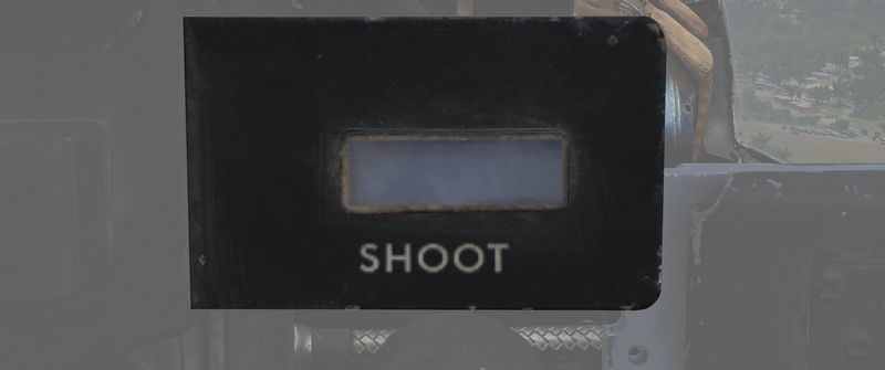
Illuminates when missile firing parameters are met. Does not illuminate when in Visual Intercept (VI) or Air-to-Ground modes.
RWR Azimuth Indicator
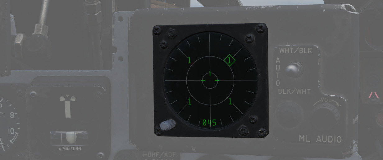
The Radar warning receiver Azimuth Indicator shows all Radar sources that are visible to the Radar warning receiver. The knob on the lower left controls the brightness of the display.
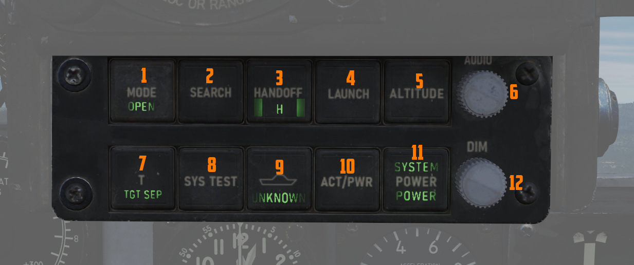
Left to it is a box with several knobs to operate the system.
For further information and button explanation, see the Radar Warning Receiver chapter.
Target Contrast Switch
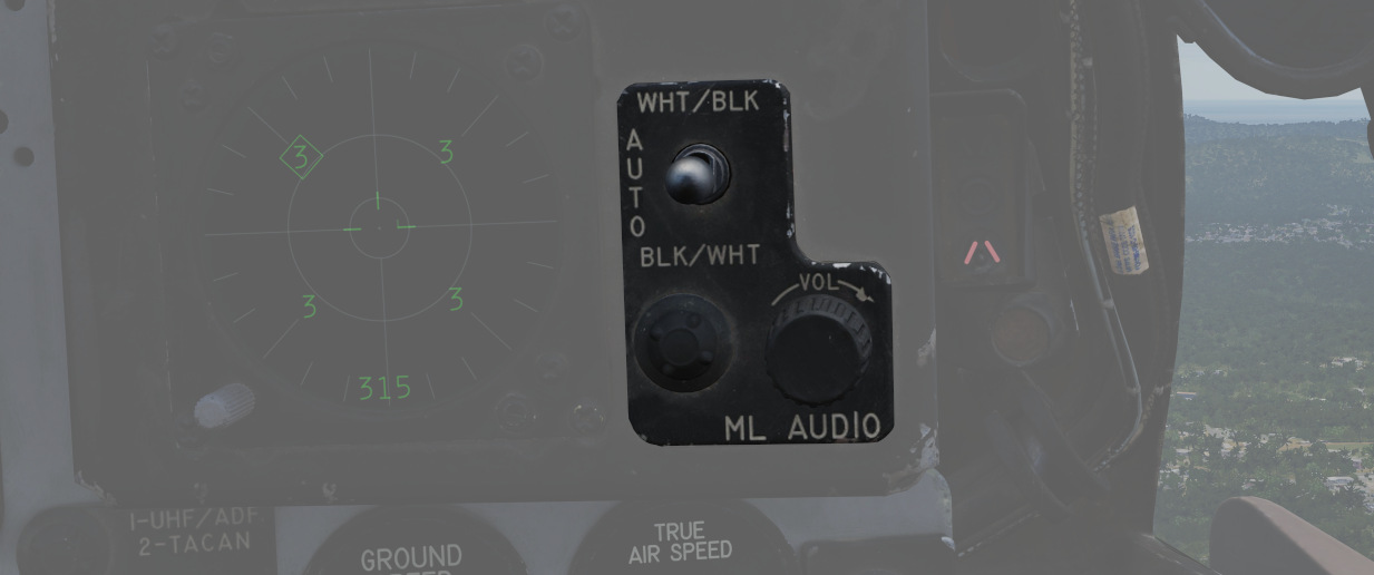
Used to select the appropriate contrast conditions for seeker acquisition with the AGM-65A Maverick and AGM-65B Maverick.
| Name | Description |
|---|---|
| WHT/BLK | Programs the missile seeker to track a light target on a dark background. |
| AUTO | Programs the missile to use its automatic tracking mode. |
| BLK/WHT | Programs the missile seeker to track a dark target on a light background. |
This does not change the polarity of the video but the coding of the seeker itself.
ML Audio Knob

Controls the volume of the Missile Launch System that plays tones to warn the WSO about being under attack.
Angle of Attack Indexer
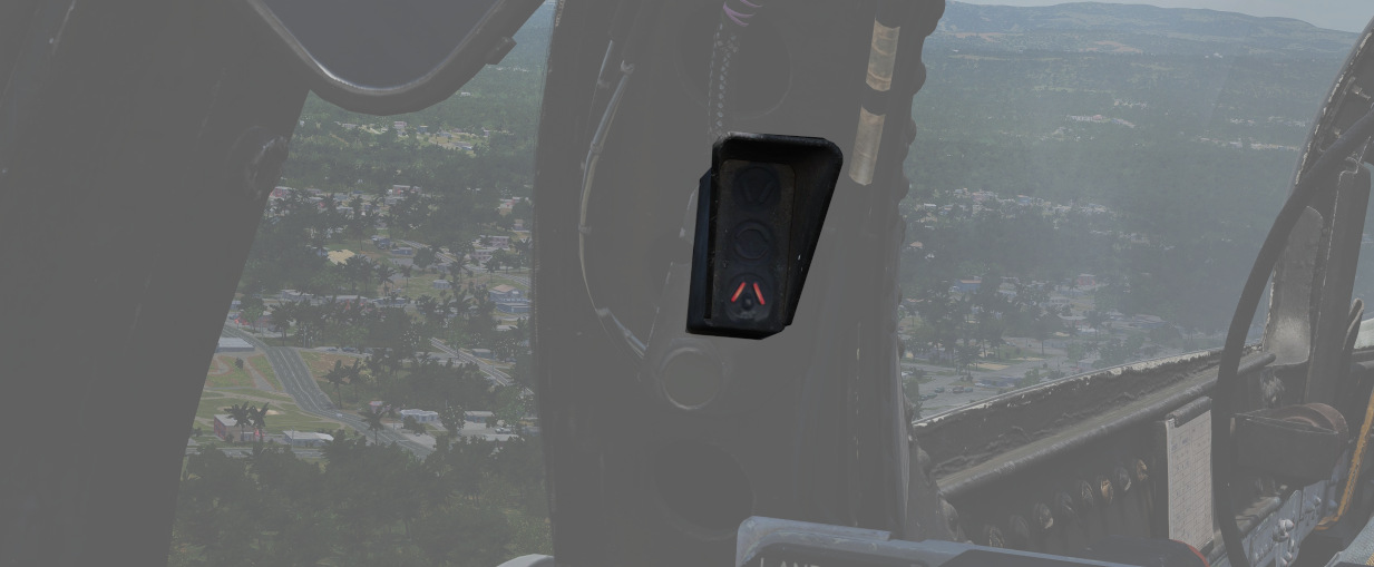
A pair of indicators to the left and right that provide quick confirmation of the current aircraft AoA state based on illuminated position and color.
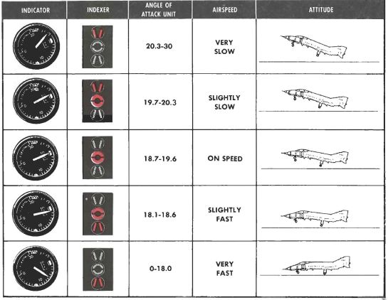
Can also indicate weapon steering cues, and an aural tone system backs up the indication with audible cues. See Angle of Attack System for details.
💡 The AoA Indexers are only lit with the right gear down.
APX-81A Activity Lights
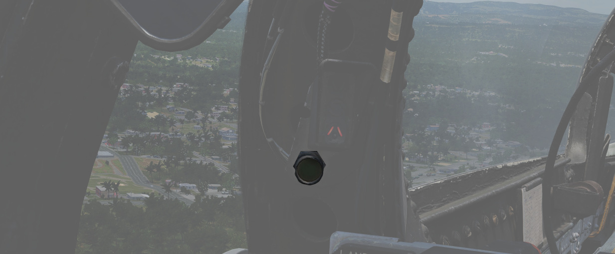
Right next to either AoA Indexer in the WSO cockpit is a light that indicates activity detected by the APX-81A Combat Tree system.
Illuminated each time the system detects IFF responses by hostile aircraft.
💡 Due to engine limitations, the activity lights only illuminate if a transponder responds to a Combat-Tree challenge send by the own aircraft.
Range (VISIDENT) Indicator
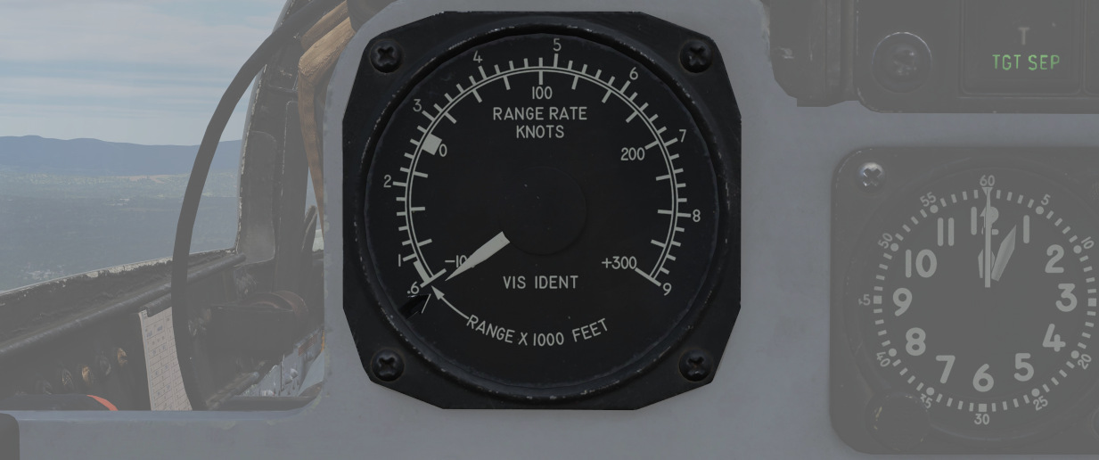
Displays accurate radar range information inside 2 miles (12000ft) and range/rate information inside 9000ft, when lock-on exists in Visual Intercept, B NAR, or B WIDE mode. When AIR-GRD is selected, the indicator is disabled.
8-Day Clock
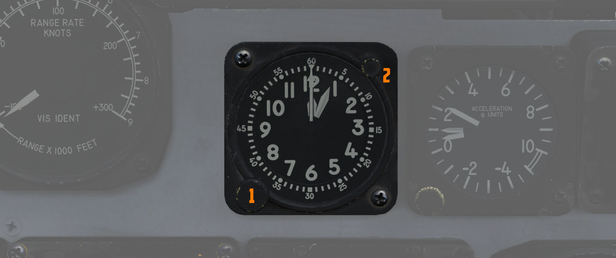
A clock is provided for the WSO, including a stopwatch function. The watch features a hour and
minute hand, and can be set by turning
the knob (
Accelerometer
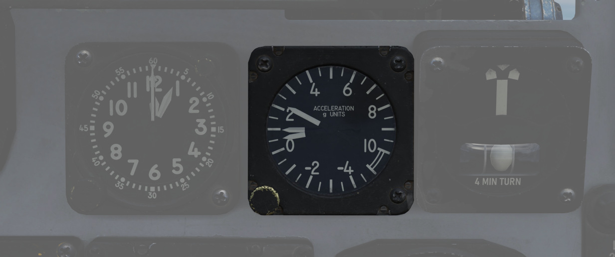
Calibrated from negative 4 to positive 10 in units of G, with three pointers - one for the current applied load, the other two show maximum positive and negative G applied during the flight. Pressing the PUSH TO SET button will reset the maximum position indicators to 1 G.
Turn Indicator
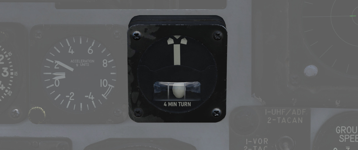
A 4-minute turn indicator, utilizing a conventional horizontally mounted gyro, accurately displays standard turn rates, resembling a conventional turn and slip indicator.
To execute a controlled turn (360° in 4 minutes), place the vertical needle over one of the indicators on either side (turn rate of 1.5 degrees per second) and ensure the slip indicator at the bottom is centered to prevent over- or under-turning due to incorrect bank.
Navigation Mode Selector Switch
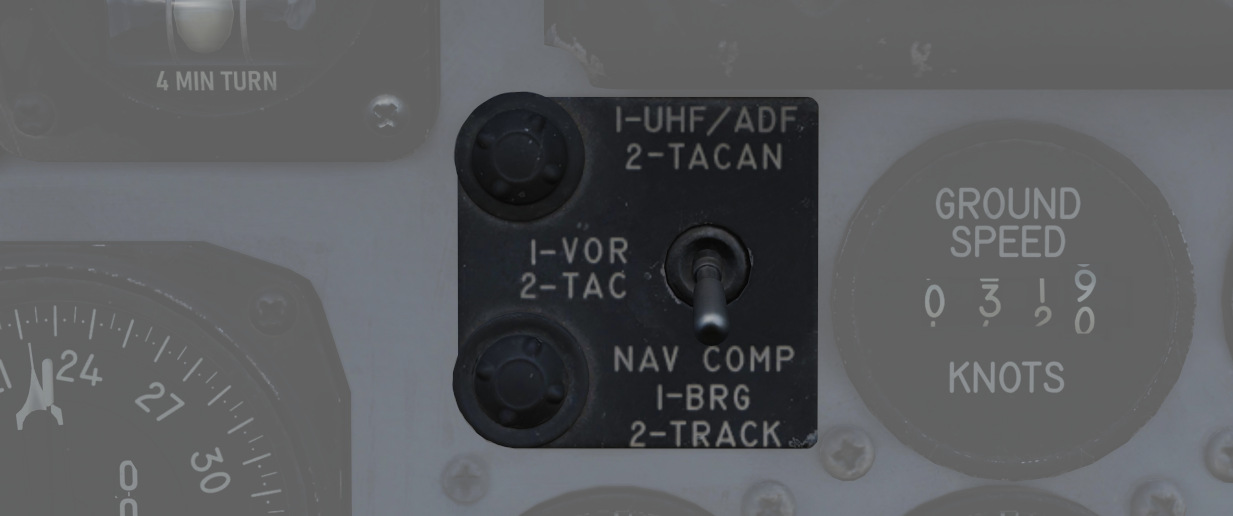
Selects the respective mode for the two BDHI needles.
| Name | Needle 1 | Needle 2 |
|---|---|---|
| Up | UHF/Automatic Direction Finding | TACAN station |
| Center | VOR Station | TACAN station |
| Down | Nav Computer mode: Bearing | Nav Computer mode: Ground track |
Ground Speed Indicator
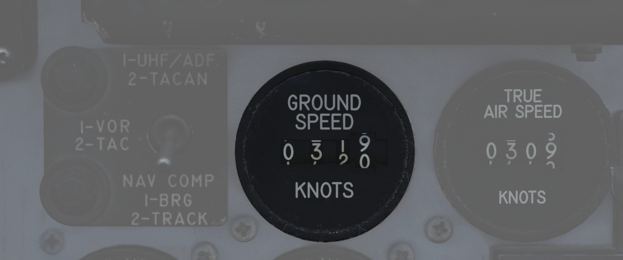
Provides the aircraft's ground speed in knots, and is calibrated from 0 to 1999 knots. Requires INS for accurate presentation. If INS is off, it can register any value of up to 150 knots when motionless on the ground.
True Airspeed Indicator
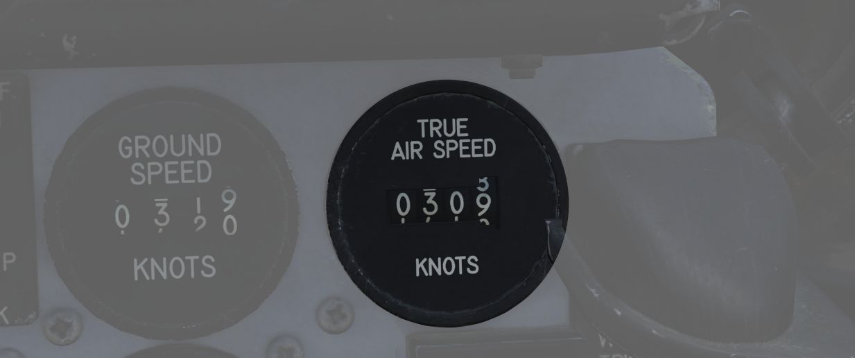
Provides the aircraft's true Airspeed in knots, and is calibrated from 150 to 1500 knots; airspeeds below this range are thus not reliable.
UHF Remote Channel Indicator
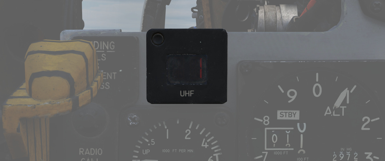
Provides the current selected channel value when the radio is set to PRESET. Otherwise, the indicator displays M if the radio is set to Manual, G when the COMM function is set as GUARD/ADF, or A when the A-3-2-T switch is in A.
Vertical Velocity Indicator
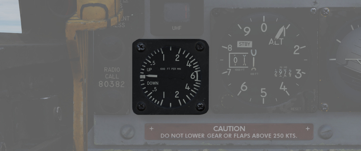
Provides the rate of climb or descent via the static pressure system referenced in thousands of feet per minute.
Altimeter
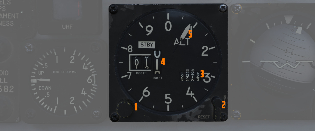
A counter-pointer style altimeter, with thousandths in the counter window (
Works in either electric (normal
operation mode) or pneumatic (STBY) mode, switchable via a spring-loaded three
position switch (
When held in RESET for more than 3 seconds, the system will be reset and moved out of STBY.
Attitude Indicator
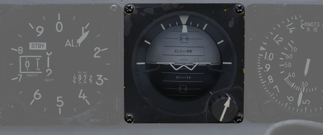
The AJB-7 provides attitude information to the Attitude Indicator found on the rear cockpit instrument panel regardless of the Reference System Selector Switch position.
A trim knob provides the ability to adjust the attitude sphere to reference the aircraft correctly.
Should power be disconnected from the indicator or AHRS, the OFF flag will display.
Airspeed and Mach Indicator
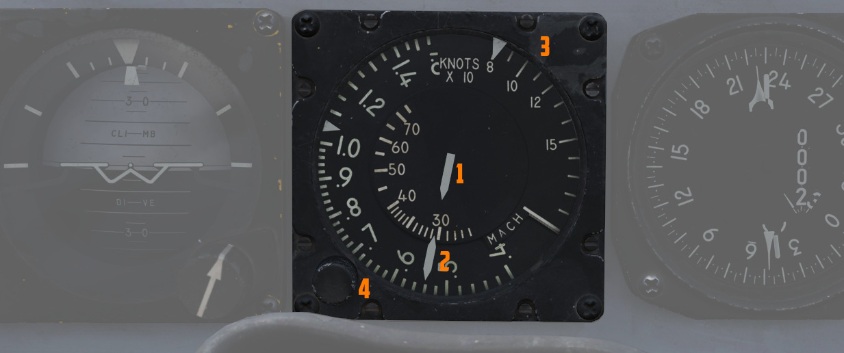
The combination of airspeed and Mach number indicator shows airspeed readings below 200 knots, and include Mach numbers on the outer ring at high speed. The indicator uses a single pointer over a fixed airspeed scale, marked from 80 to 850 knots, with a moving Mach scale presenting from Mach 0.4 to 2.5.
A pair of movable reference markers
is available with the knob (
The (
Bearing Distance Heading Indicator (BDHI)
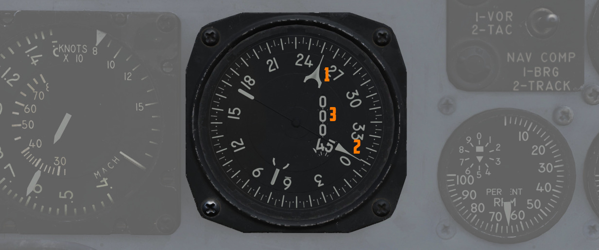
The Bearing Distance Heading Indicator, or BDHI, presents navigation information as entered by the WSO, provided with two needles (termed the No. 1 and No. 2 pointers). See Navigation Mode Selector Switch for Needle Explanation.
When the upper position of the Navigation Mode Selector Switch is selected by the WSO to TACAN/ADF/UHF, the no. 1 pointer indicates UHF bearing, and the no. 2 pointer indicates the TACAN bearing. If there is no TACAN signal, both pointers indicate the ADF bearing.
With the middle position selected - VOR/TAC, the no. 1 pointer indicates the VOR bearing, the no. 2 pointer indicates the TACAN bearing, and the range indicator provides distance to the TACAN station. In the absence of a TACAN signal, both pointers indicate the VOR station.
In the lower position, NAV COMP, the no. 1 pointer indicates bearing to the navigation computer target coordinates, and the No. 2 pointer indicates magnetic ground track.
A vertical readout (
Tachometers
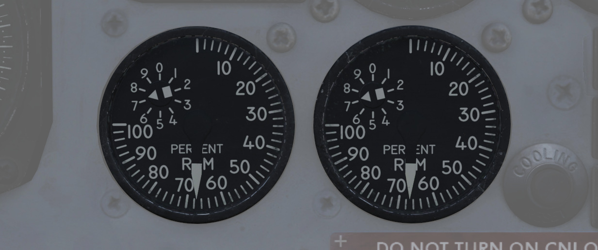
A percentage-noting Tachometer is provided for each engine, including an inset wheel for accurate display of single digits. Normal values are 65% for idle, 95% in full MIL power and 105% for full afterburner.
Canopy Unlocked Warning Lamp
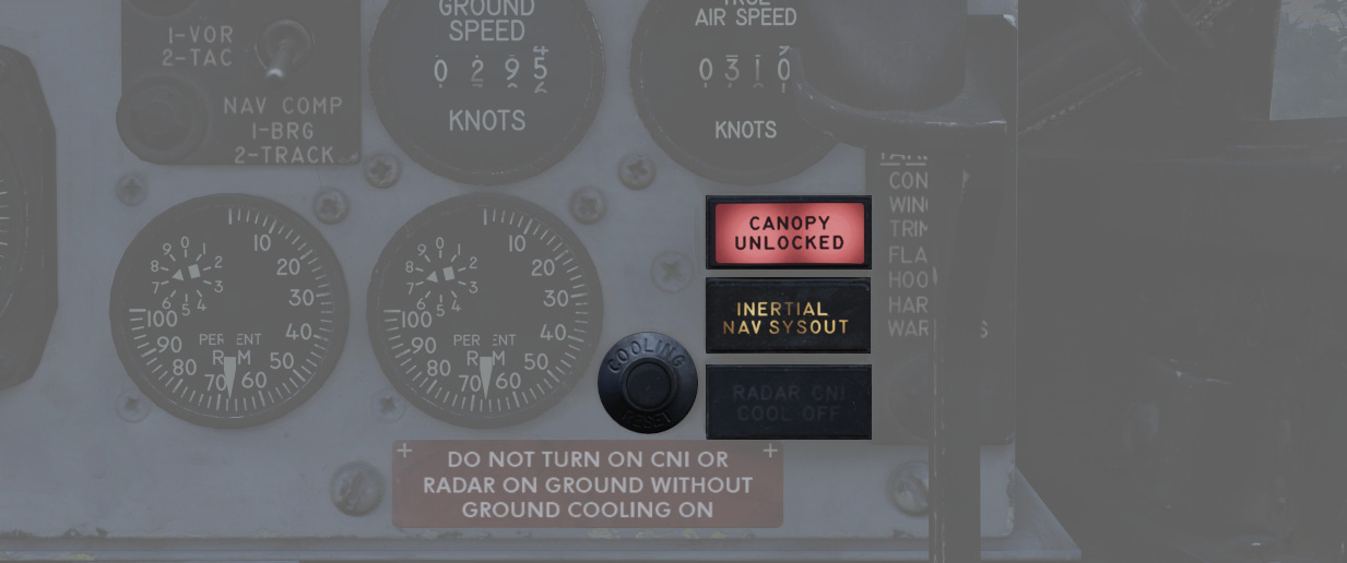
Illuminates when the canopy is unlocked. To reset the lamp, close and lock the rear canopy.
Inertial Nav Sys Out Lamp
Illuminates when the INS system is in a failure state. To reset the INS, refer to the 3.3.2 Inertial Navigation System chapter.
Radar CNI Cool Off Lamp
Illuminates to indicate an over-temperature situation in the avionics cooling system, most likely caused by a bleed air duct failure.
If the light is illuminated, reduce the airspeed and wait 15 seconds. Then, press the CNI cooling reset button next to it.
Should the light stay illuminated, remain at reduced power and speed and land as soon as practical.
Cooling Reset Button
Resets the CNI cooling system.