Aft Section
The aft section of the left console has the intercom and countermeasure controls.
Boarding Steps Indicator
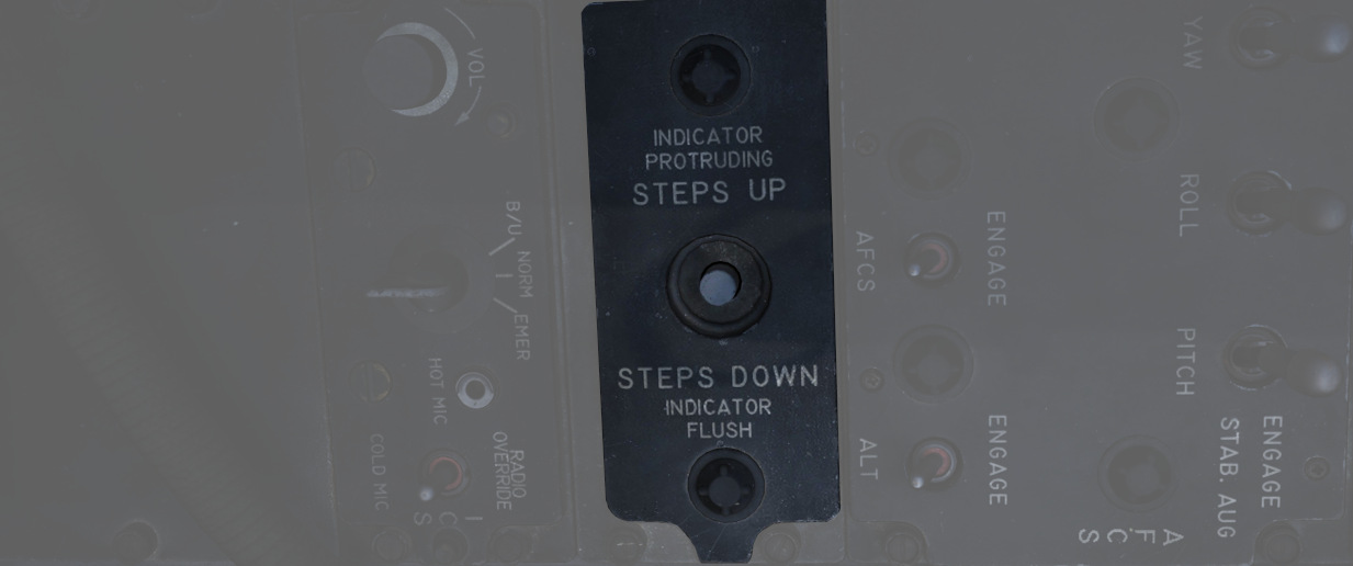
Used to visually confirm the state of the integrated boarding steps. With the white post up, steps are stowed, whereas steps are deployed if post is down and flush with the panel recess. The boarding steps and ladder are moved by the crew chief.
Intercom System Control Panel
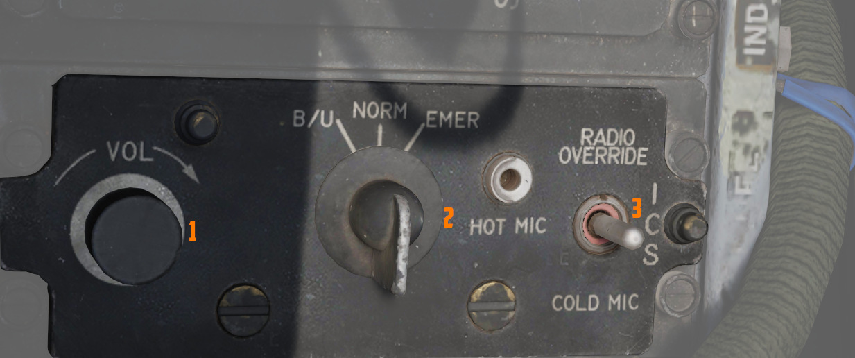
Volume Control Knob
The volume control knob (
Amplifier Select Knob
The amplifier select knob (
| Name | Description |
|---|---|
| B/U | Backup headset amplifier provides audio. |
| NORM | Primary headset amplifier provides audio. |
| EMER | Uses the amplifier from opposite cockpit; all and only audio including radio received to that cockpit is heard. |
Function Selector Switch
The function selector switch (
| Name | Description |
|---|---|
| COLD MIC | Mic switch on throttle must be held to activate intercom. |
| HOT MIC | Voice automatically transmitted on intercom. |
| RADIO OVERRIDE | Voice automatically transmitted on intercom. All volumes but Shrike tone and Stall Warning are reduced in volume. |
AN/ALE-40 Programmer
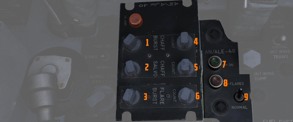
The panel features 6 knobs to control chaff and flare dispensing, as well as two lamps and a switch.
Knobs
There are two important definitions to know when setting up the countermeasures:
- BURST - single dispense signal
- SALVO - group of bursts
Using the six knobs placed on the programmer you can adjust following parameters:
| Category | Knob | Values | Description |
|---|---|---|---|
| CHAFF BURST | COUNT ( | 1, 2, 3, 4, 6, 8 | quantity of bursts (per salvo) |
| INTERVAL ( | 0.1, 0.2, 0.3, 0.4 | time interval between each burst | |
| CHAFF SALVO | COUNT ( | 1, 2, 4, 8, C (continuous) | number of salvos |
| INTERVAL ( | 1, 2, 3, 4, 5, 8, R (random) | time interval between each salvo | |
| FLARE BURST | COUNT ( | 1, 2, 4, 8, C (continuous) | quantity of bursts |
| INTERVAL ( | 3, 4, 6, 8, 10 | time interval between each burst |
💡 All intervals are expressed in seconds.
Flares Select Switch
The flares select switch (
In the NORMAL setting, countermeasures are released according to the combined settings of the CCU and the Programmer.
FLARES position allows the pilot to dispense a single flare with each dispense button press regardless of CCU and Programmer settings.
Power On Indicator Light
The power on indicator light (
Flares Indicator Light
The flares indicator light (
Gyro Fast Erect Switch
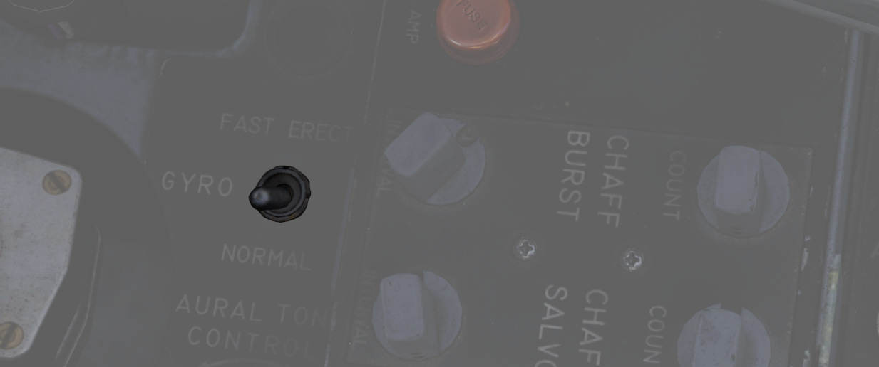
Selects gyro operation. FAST ERECT can be used momentarily to correct gyro deviations.
See 3.11.4. ARBCS for details.
Aural Tone Control
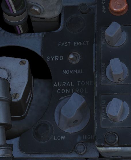
Knob to control the volume for weapon tones, such as the Sidewinder seeker head.
Anti-G Suit Control Valve
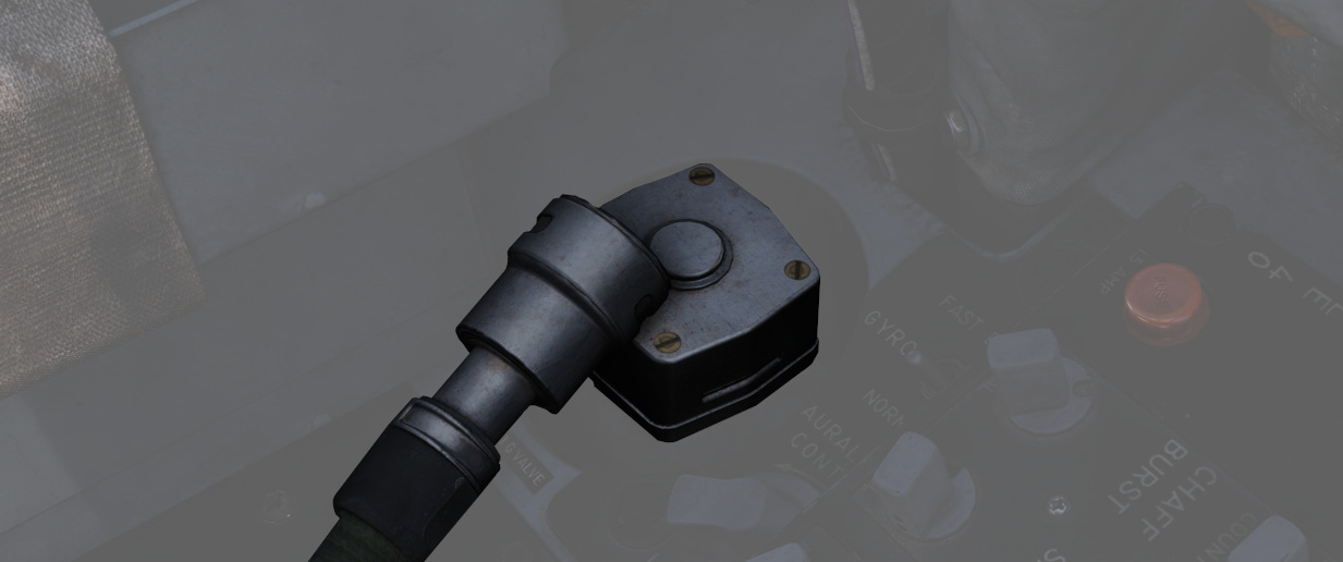
The anti-G system delivers low-pressure auxiliary air to the anti-G suits, with air passing through the anti-G suit control valve before reaching the suit. The suit remains deflated up to approximately 1.5 G, and as G forces reach or exceed this level, air flows into the suit proportionally. The suit stays inflated in relation to constant G forces and begins to deflate as G forces decrease.
A manual inflation button in the anti-G suit control valve enables the crew to manually inflate the suit for system checks or fatigue relief. A pressure relief valve within the system activates at approximately 11 psi, serving as a safety backup in case of malfunction. The system operates automatically whenever an engine is running, ensuring continuous support for the wearer during varying G-force conditions.