Center Section
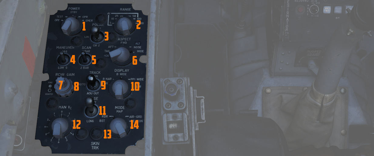
The center area of the left console features the radar control and countermeasure panel.
Radar Set Control Panel
See Radar Set Control Panel section for a more detailed description of all the functions below.
Power Knob
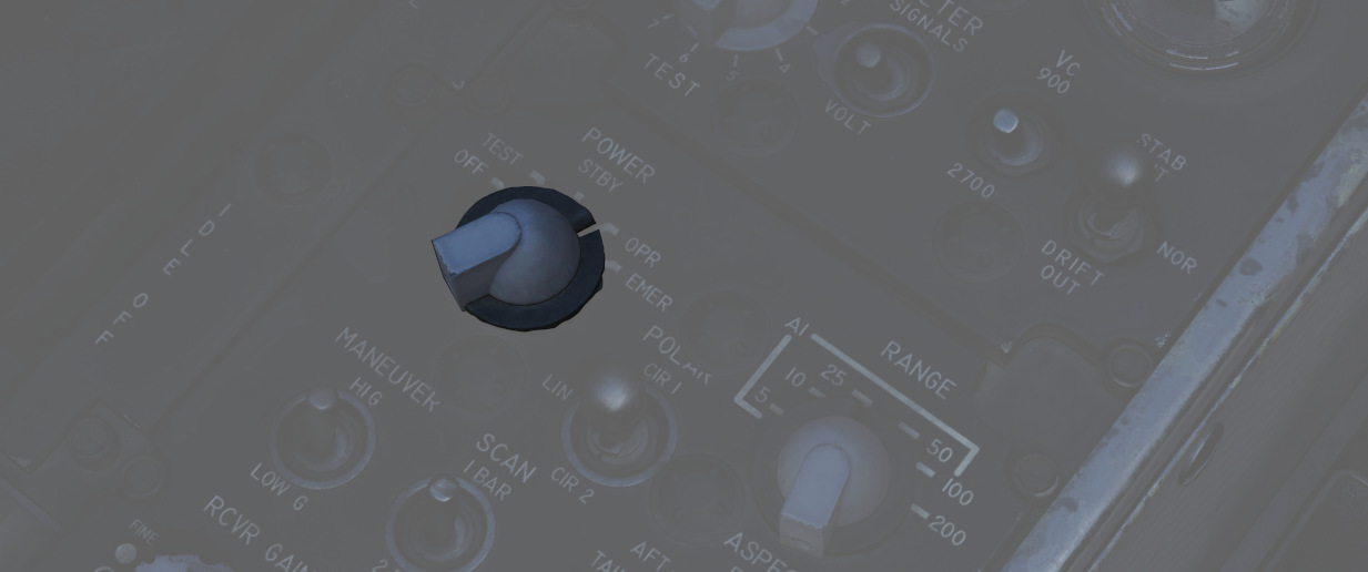
Five position rotary switch (
| Name | Description |
|---|---|
| OFF | Powers radar off. |
| TEST | Applies voltage to control monitor power and provides BIT-test functions 1 through 6. |
| STBY | Power applied to radar, remains in a non-transmitting standby state. |
| OPR | System is fully operational. |
| EMER | Overrides the time delay, pressure, and temperature restrictions to allow radar operation. |
See the Radar Power Section for more details.
Polar Switch
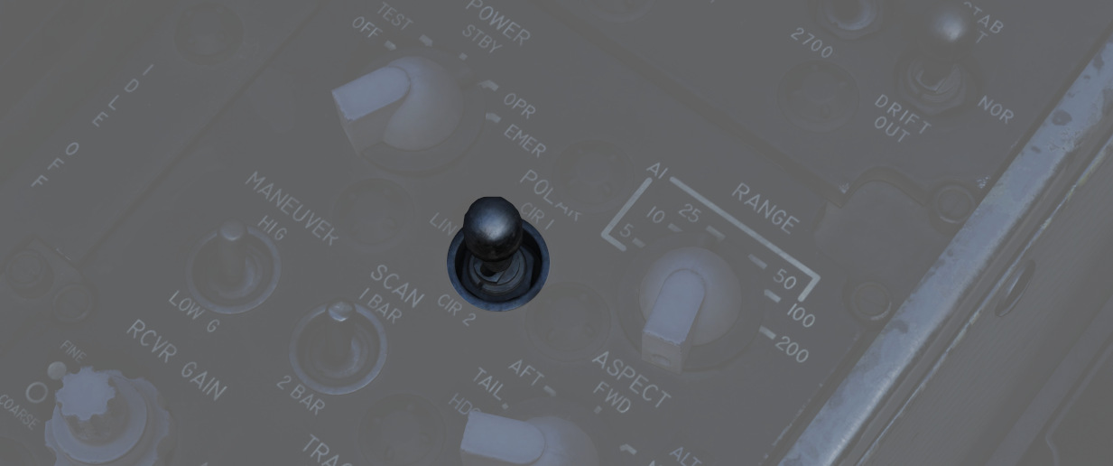
The three-position switch (
See Radar Polarization Knob Section for more details.
Range Knob
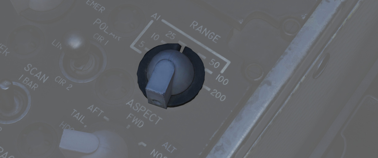
The rotary switch (
See the Radar Range Knob Section for more details.
Maneuver Switch
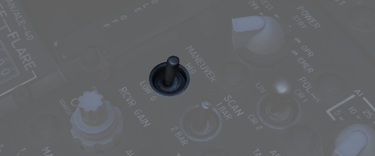
The two-position switch (
See Radar Maneuver Knob Section
Bar Scan Switch
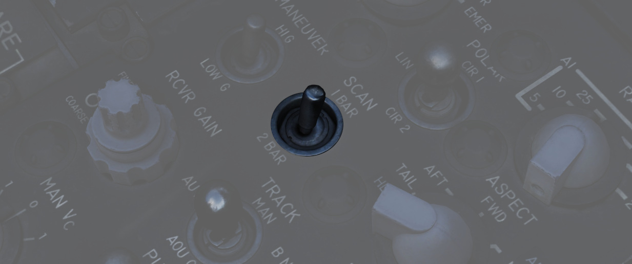
The two position switch (
See Radar Scan Switch Section for more details
Aspect Knob
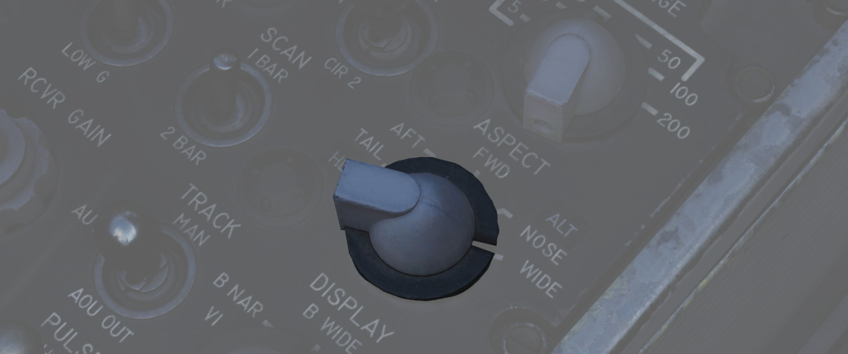
The rotary switch (
See Aspect Knob Section for more details
Receiver Gain Knobs (RCVR GAIN)
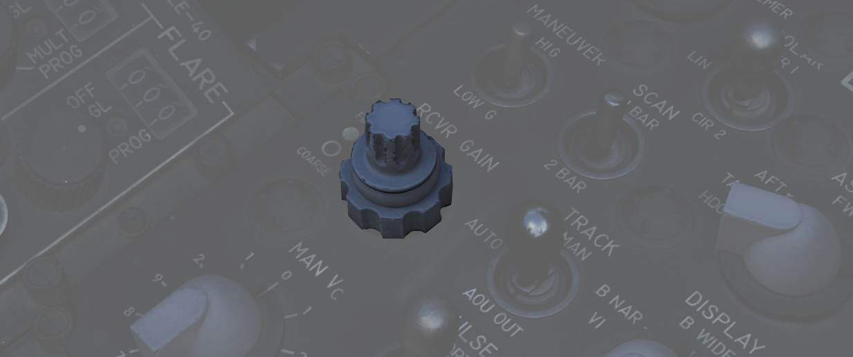
Coarse (outer ring,
See Receiver Gain Knob Section for more details
Track Switch
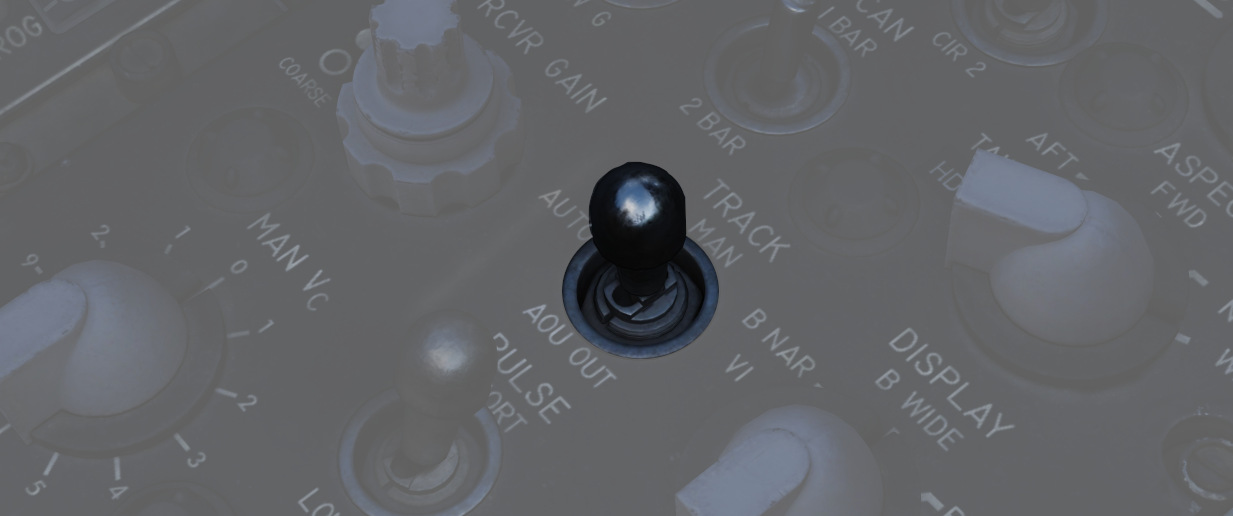
The three position switch (
See Radar Track Switch Section for more details
Display Knob
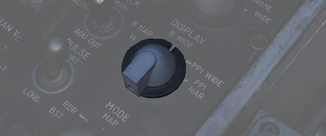
The rotary switch (
| Name | Description |
|---|---|
| B WIDE | Selects 120-degree B-sweep for search. Half-action places the sweep under the manual Antenna Hand Control stick. |
| B NAR | Selects a 45-degree B-sweep sector for search, which is manually shifted with the Antenna Hand Control stick. |
| PPI WIDE | Selects a 120-degree wide plan position indicator sweep for MAP mode. |
| PPI NAR | Selects a 45-degree plan position indicator sweep that can be shifted with the Antenna Hand Control stick. |
| VI | Provides pure pursuit guidance to a locked target for Visual Intercept; a break X will appear at 1000' range. |
Manual Vc Knob
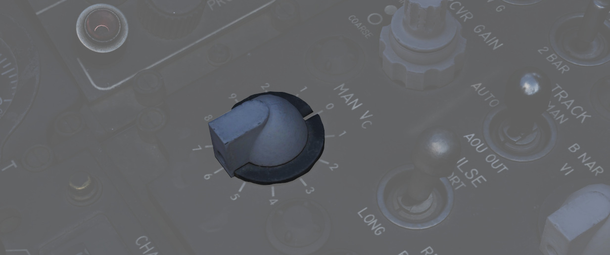
A 12 position switch (
The numbers are multiplied by 100 knots, while closure means closing in to the F-4 and opening means the target is flying away from the F-4.
See MAN Vc Knob Section for more details
Pulse Switch
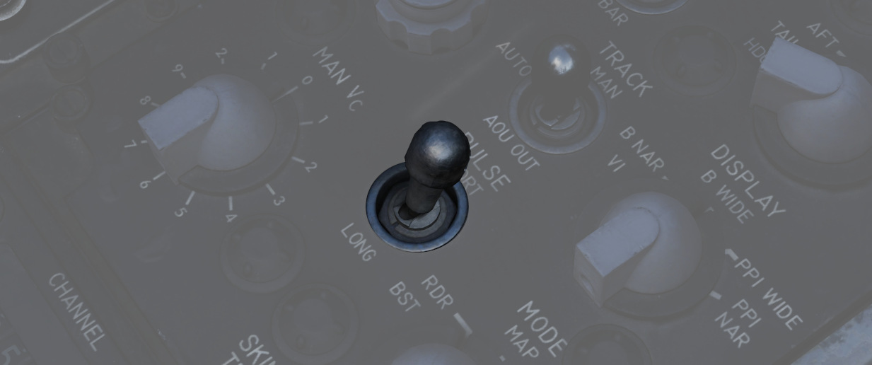
Three position switch (
| Name | Description |
|---|---|
| AUTO | Uses Power Level Mode Switching to determine the best Pulse selection. Selects short pulse is used for acquire and track. |
| LONG | Wide pulse width and low PRF, allowing maximum range detection; no track automatic pulse adjustment. |
| SHORT | Narrow pulse width with high PRF for increased close-range performance. |
See Pulse Switch Section for more details
Mode Knob
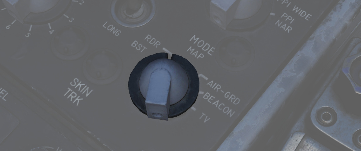
A six position rotary switch (
| Name | Description |
|---|---|
| BST | Air-to-Air boresight with antenna aligned radar boresight line and optical sight with sight in A/A. |
| RDR | Search Mode with Feedhorn Nutation (wider beam-width) mode. |
| MAP | Search Mode without Feedhorn Nutation (narrower beam-width) |
| AIR-GRD | Air-to-Ground boresight, Tracks range of illuminated ground, radar is boresighted to the radar boresight line with drift compensation. |
| BEACON | Radar receives and displays signals from ground or airborne beacon transponders for navigation. |
| TV | Not used with DSCG. De-tunes AIM-7 if selected, preventing Sparrows from guiding. |
💡 Beacons are currently not implemented in DCS and thus can't be used
See Mode Knob Section for more details
Skin Track Light
Lamp (
Throttles
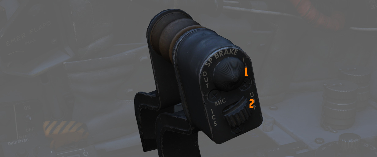
The throttle arrangement for each engine in the F-4E Phantom II is located on the front and rear cockpit left console. Mechanical linkage transmits throttle movement to the engine fuel control. The rear cockpit throttle does not enable the afterburner. Located on the rear throttle is a speed brake switch and a mic switch.
Speed Brake
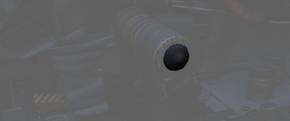
The Speed Brakes are actuated by a three-position switch (
For further information, see the 3.1.2 Flight Control Surfaces chapter.
Mic Switch
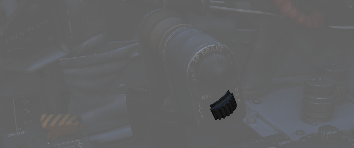
The microphone switch (
AN/ALE-40 Cockpit Control Unit (CCU)
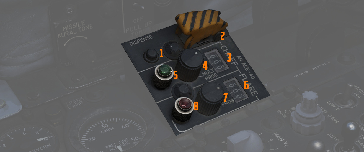
The CCU is a primary control panel of the Countermeasures System.
It is used to select different modes of operation and gives the WSO the ability to dispense countermeasures.
For further information, see CCU.
Dispense Button
The push button (
Ripple Switch
Guarded by a cover (
💡 After around 10 seconds, all flares have been dispensed.
Counters
Indicate quantity of chaff (
They are automatically set by the ground crew when rearming.
Chaff Mode Knob
A rotary switch knob (
| Name | Description |
|---|---|
| OFF | Chaff system inactive. |
| SGL | A single burst commanded when dispense button pressed. |
| MULT | A salvo commanded according to programmer when either dispense button pressed. |
| PROG | Multiple salvos commanded according to programmer when either dispense button pressed. |
Flare Mode Knob
A rotary switch knob (
| Name | Description |
|---|---|
| OFF | Flare system inactive. |
| SGL | A single burst commanded when dispense button pressed. |
| PROG | A salvo commanded according to programmer when either dispense button pressed. |
Indicator Lights
Illuminates (5 and 8) whenever a mode is selected on the respective countermeasure mode knob.
Can be rotated to dim and pressed to test.