Right Main Panel
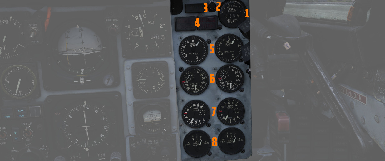
The right main panel offers a good overview of all the needed engine data as well as of your defensive
Radar warning receiver (RWR). There is also the fuel gauge (
RWR Azimuth Indicator
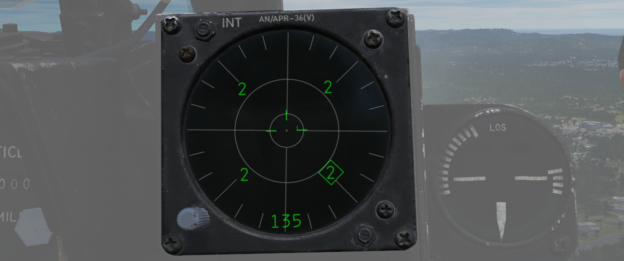
The Radar warning receiver Azimuth Indicator shows all Radar sources that are visible to the Radar warning receiver. The knob controls the brightness of the display.
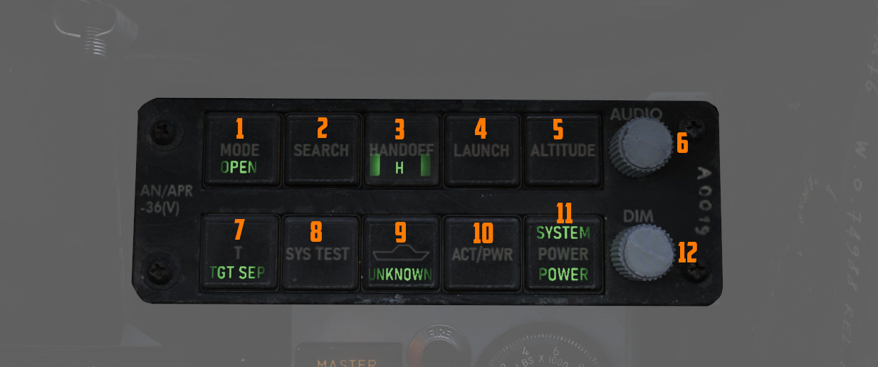
Below is a box with several knobs to operate the system.
For further information and button explanation, see the Radar Warning Receiver chapter.
Azimuth-Elevation Indicator
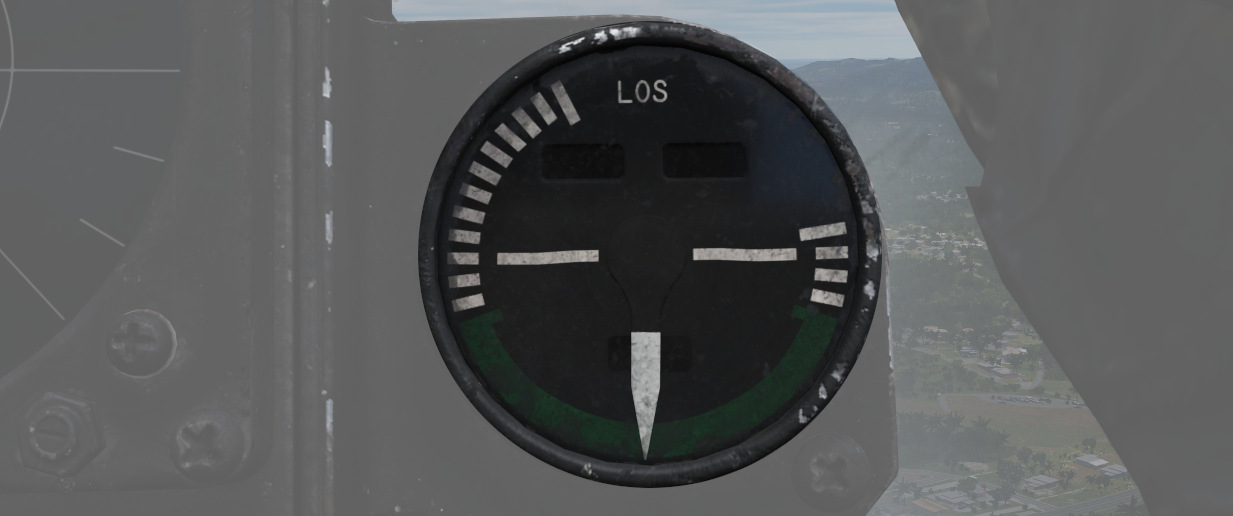
The Azimuth-Elevation Indicator, or also Line-Of-Sight Indicator, is the main instrument for the pilot to assess the current attitude of the Pave Spike Targeting Pod in order to keep the line of sight within the operational limits.
The needle shows the pod's roll position from -160° (CW) to +110° (CCW).
Three flags indicate the elevation:
- green: -120° to -155°
- yellow: -155° to -160°
- red: -160° or beyond
If the needle is kept within the green labelled range and neither the yellow or red flags are shown, the view will not be obstructed by the pod or the aircraft.
Master Caution Light
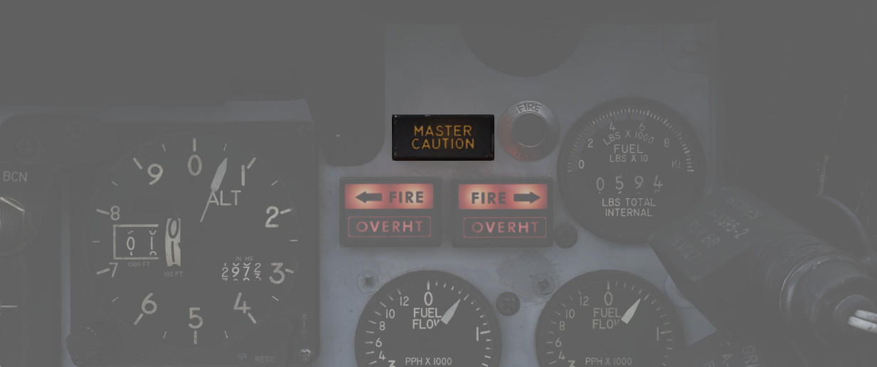
The Master Caution light illuminates to provide the pilot warning of a condition requiring attention, directing them to look at the telelight panel for additional information. The Master Caution lamp is reset by correcting the condition, or pressing the Master Caution Reset button on the generator control panel.
Fire Test Button
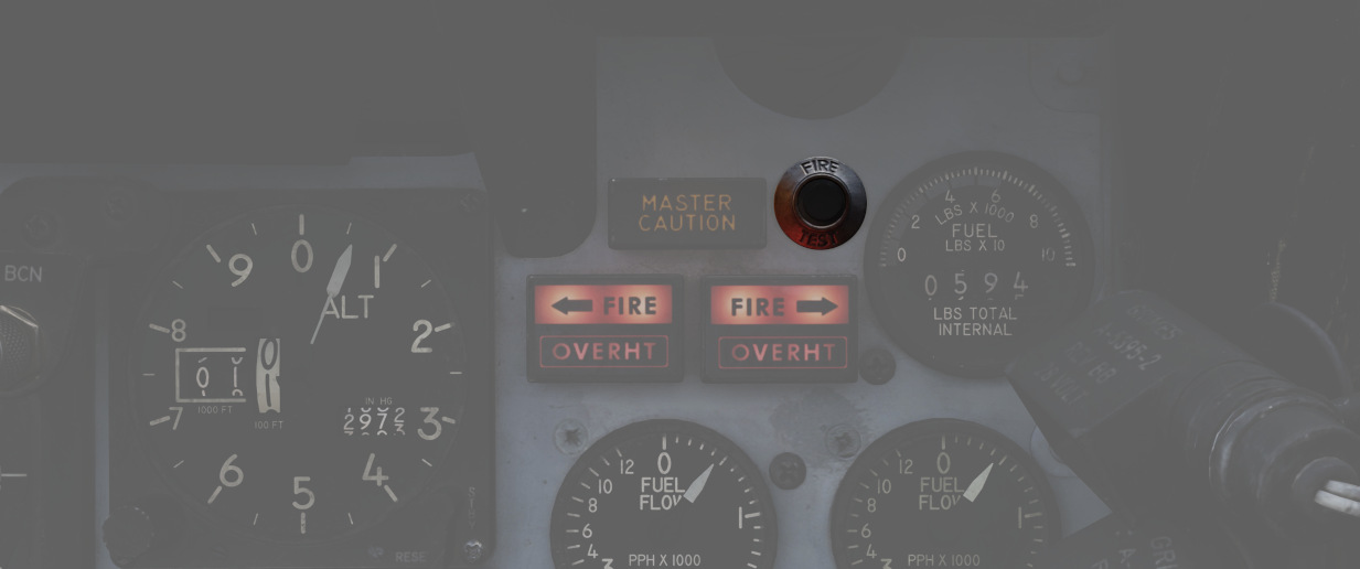
When pressed, this button tests for functionality of the FIRE and OVRHT lamps. Under normal conditions, all four lights should light up as long as the button is pressed down. If a lamp does not light up, it is likely broken and cannot be trusted to indicate a fire condition anymore.
The button can also be used in conjunction with the Warning Lights Test switch to confirm the detection and continuity performance of the fire and overheat warning systems.
Holding the Warning Lights Test switch in the WARN TEST position, then simultaneously pressing and releasing the Fire Test Button performs the test. Proper system function is confirmed with the four FIRE and OVRHT lamps off while the Fire Test Button is pressed, then illuminating when it is released.
Fire/Overheat Warning Lamps
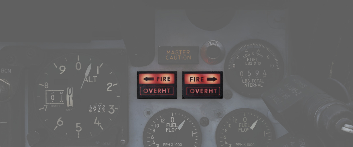
The Fire and Overheat Warning Lamps, one for each engine, are a pair of two-position indicators that illuminate when a fire condition is detected in the engine compartment (FIRE), or an overheat condition is detected in the exhaust nozzle section (OVRHT).
Fuel Quantity Indicator
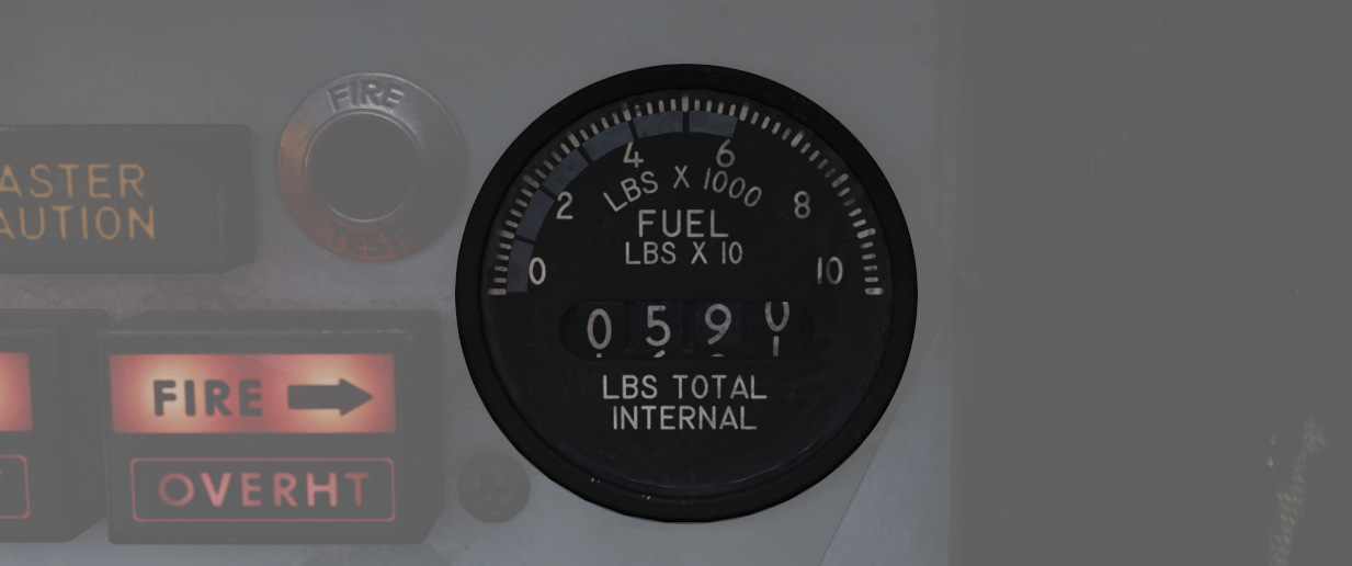
The Fuel Quantity Indicator provides two different indications of total usable internal fuel to confirm the proper transfer function between the seven internal fuel cells, as well as any external loaded tanks.
On the upper half, it displays the total fuselage fuel with a white tape on a scale marked 0 to 10 (times 1000 lbs). This readout includes cells 1 through 6, while excluding the reserve tank 7, both internal wing tanks and also any externally loaded tanks. The image shows the tape around label 6, indicating a total internal fuel of around 6000 lbs.
Additionally, a counter displays the entire internal fuel in 10 lb increments. That is, cells 1 through 7 and also the two internal wing tanks. Any external tanks are excluded as well. The example has the counter reading 0590, indicating 5900 lb of internal fuel.
💡 External tank fuel quantity can not be checked. See 3.2.2. External Tanks Fuel Lights to check if they are empty.
As a general guidance, Bingo fuel is around 4000 pounds, while Joker fuel is at 6000 lb.
For more detailed information, see 3.2.2 Fuel system chapter.
Fuel Flow Gauges
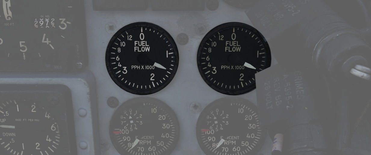
A pair of fuel flow indicators is provided, one for each engine, presenting pounds per hour rate from 0 to 12, in 1000 lb increments. Flow indications are for basic, non-afterburning thrust. In afterburner, the flow rate is roughly four times the displayed flow rate.
Tachometers
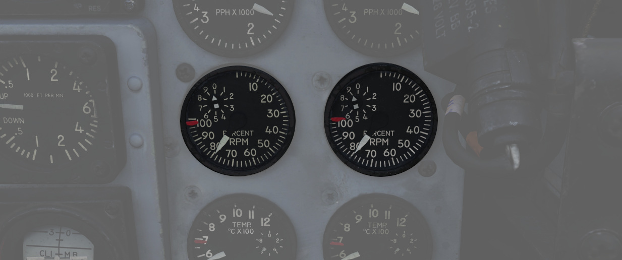
A percentage-noting Tachometer is provided for each engine, including an inset wheel for accurate display of single digits. Normal values are 65% for idle, 95% in full MIL power and 105% for full afterburner.
Exhaust Gas Temperature Gauges
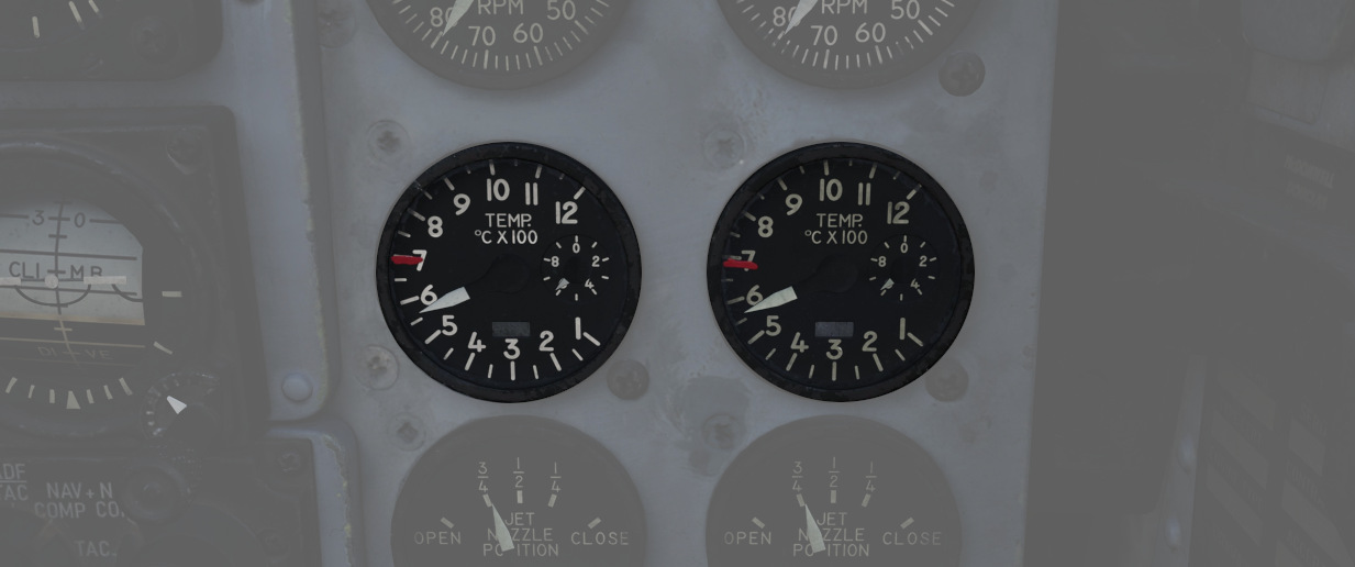
Exhaust Gas Temperature gauges are provided for each engine. The gauges have two needles - a large needle providing increments of 0 to 12 in multiples of 100 degrees Celsius, and a smaller needle presenting increments of 0-10 in multiples of 10 degrees Celsius. Temperatures are measured at the exit of the turbine unit.
Exhaust Nozzle Position Indicators
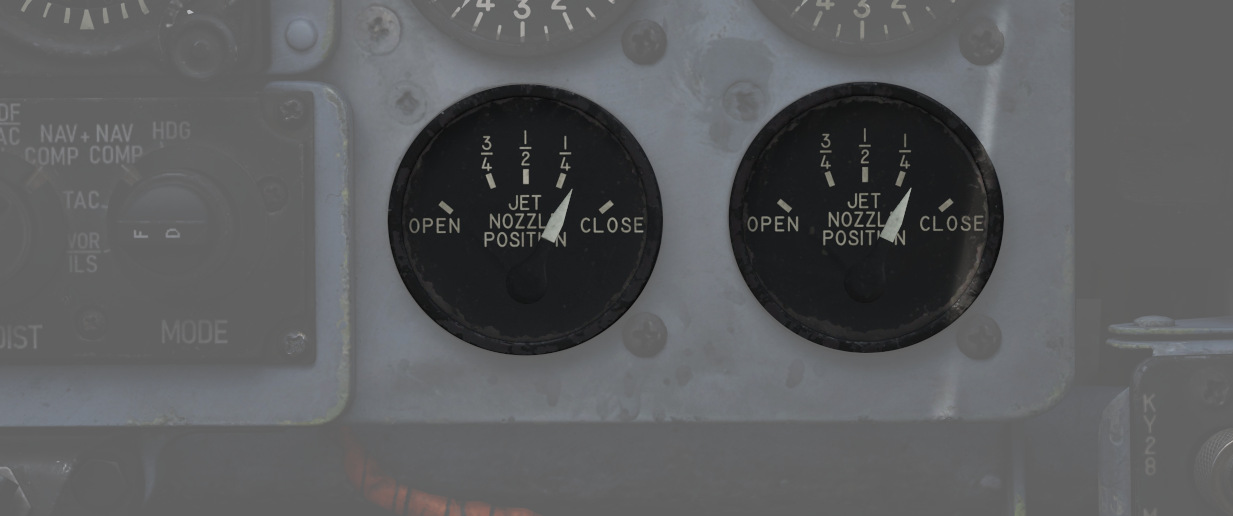
A combined Nozzle Position Indicator is provided with two needles, one for each engine on their respective side, to confirm balanced nozzle position and scheduling relative to throttle position. The gauge provides four zones relative to the nozzles being in their fully open configuration (needle fully left), or their maximum closed configuration (needle fully right). At idle, the indication will be roughly 7/8ths open, and schedules down as the throttle is increased. Position in the afterburner region will moderate to maintain safe EGT levels.