Flight Director Group
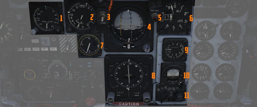
The flight director group provides the pilot with all necessary instruments to fly the
aircraft even
in a bad weather situation. It contains the Radar Altimeter (
Radar Altimeter
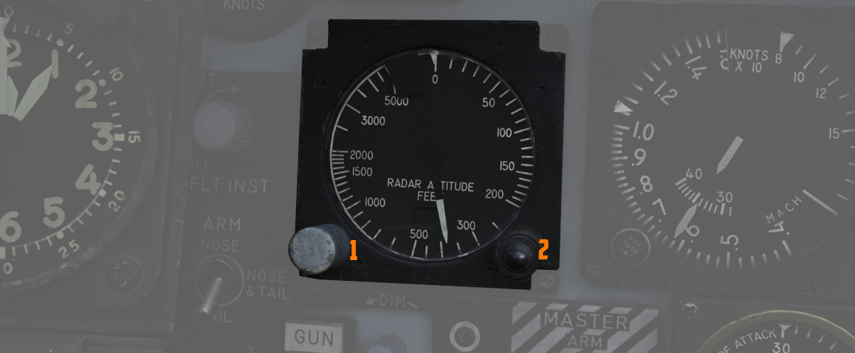
Terrain relative accurate height information up to 5000 ft, functions to 30
degrees of bank angle or 35 degrees of pitch. Clockwise rotation of the function
control switch (
Airspeed and Mach Indicator
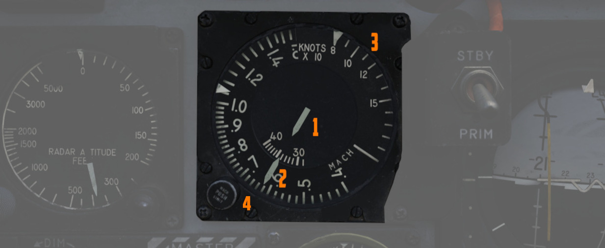
The combination airspeed and Mach number indicator shows airspeed readings below
200 knots, and include Mach numbers on the outer ring at high speed. The indicator uses a
single
pointer over a fixed airspeed scale, marked from 80 to 850 knots, with a moving
Mach scale (
Angle of Attack Indicator
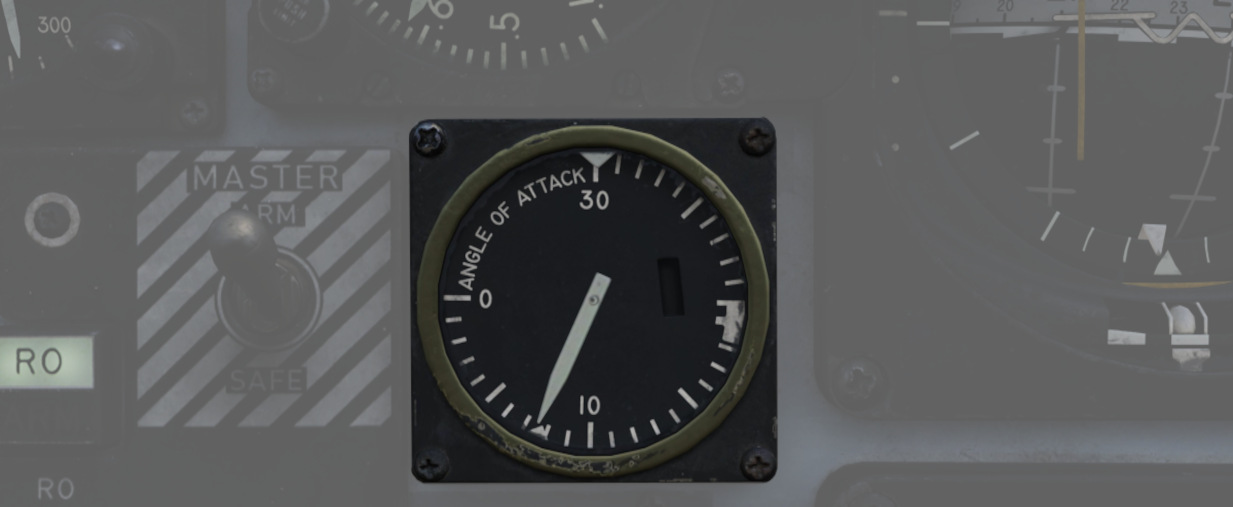
Drawing relative wind information from the landing-gear adjacent AoA probe, the AoA indicator offers conditional reference for cruise (7.9 units), approach (19.2 units), and stall (30 units). Because of the AoA probe to the nose gear door and subsequent airflow disturbance when the gear is lowered, actual aircraft AoA is approximately 1 unit higher than indicated, and ON SPEED AoA is roughly 5 knots slower than the given value.
When indicator power is offline due to electrical system configuration or damage, an OFF flag will appear in the window on the face of the gauge. The AoA indicator contains switches that light the indexer lights and actuate the stall warning vibrator.
Reference System Selector Switch
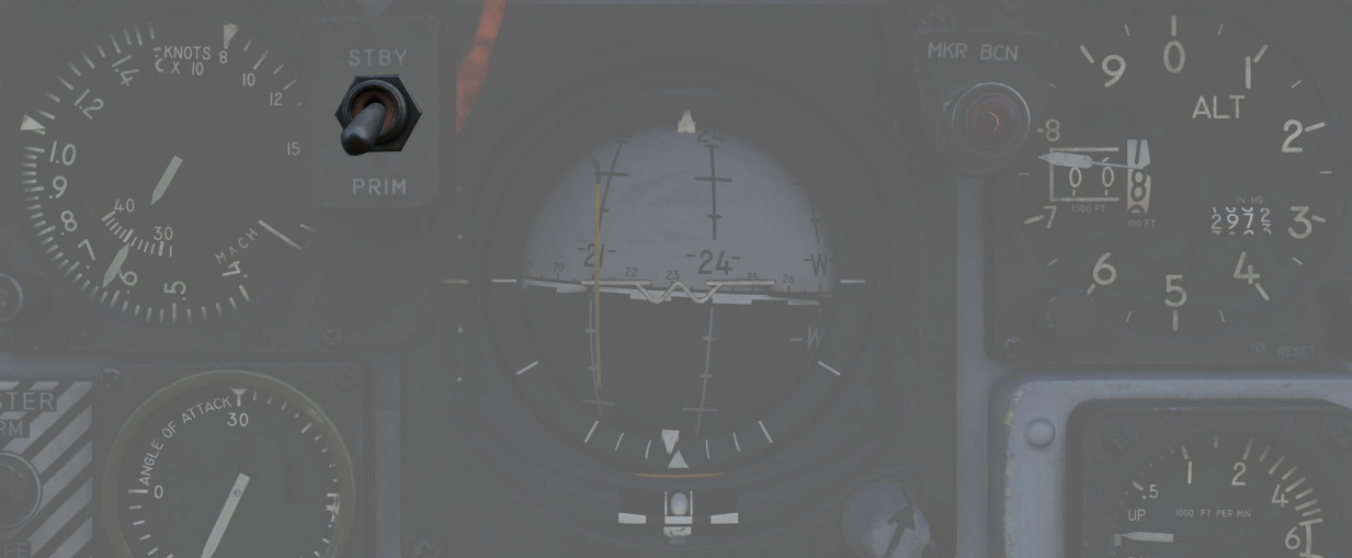
Toggles between the inertial navigation set and AN/AJB-7 displacement gyroscope for attitude information. When set to PRIM, the inertial navigation set provides azimuth and attitude data to the ADI; when on STBY, AN/AJB-7 supplies this information. Azimuth data also feeds into the HSI and BDHI (rear cockpit). Additionally, attitude details are sent to the fire control system.
💡 Inertial information requires the inertial navigator control panel's switch to be on NAV.
When transitioning between STBY and PRIM, immediate attitude information may show unusual gyrations on the attitude director indicator due to initial erection. Rapid turns (above 15° per minute) may temporarily disrupt accurate heading information and automatic synchronization of heading information. If the heading information doesn't resync itself after flying straight and level again for approximately 20 seconds, a manual synchronization is required. This can be done by flying in a straight and level flight for about 20 seconds and turning the Mode Selector Knob to the spring-loaded SYNC position for approximately 3 seconds.
Attitude Director Indicator
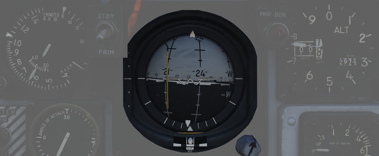
Includes an attitude sphere, turn indicator, steering bars, miniature aircraft, glide-slope pointer, flags, and pitch trim knob. It displays pitch, bank, and heading from the selected reference system and allows pitch adjustment via the trim knob. The turn indicator relies on a gyro from the AN/AJB-7 system. The steering bars offer Flight Director guidance for heading interception, navigation, and ILS approaches. The glide-slope pointer provides vertical guidance information during an ILS approach.
Marker Beacon Lamp
![]()
This lamp illuminates whenever flying over a marker beacon station, provided the VOR/ILS system has been activated. Additionally, an audio cue is played through the intercom system.
The lamp can be rotated to dim and pushed to test.
Horizontal Situation Indicator
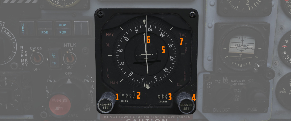
Presents a horizontal view of the navigation situation relative to the aircraft, indicated by an aircraft symbol and a lubber line showing the current aircraft heading.
Knobs
The knob on the lower left (
Compass Card
A rotating element (
It provides a reference for the aircraft's heading relative to magnetic north.
Bearing Pointer
Indicates the magnetic bearing to a selected navigation aid (Nav Comp, VOR, TACAN, or ADF).
Course Arrow and Deviation Indicator
The direction towards which the arrow (
In HDG mode, it indicates the aircraft's magnetic heading, and in NAV COMP mode, it points to the aircraft's magnetic ground track.
The Deviation Indicator provides visual feedback on the aircraft's deviation from the selected course. It shows deviation from a TACAN course in TAC mode or deviation from a VOR radial in VOR/ILS mode when VOR is tuned, and deviation from an ILS localizer signal in VOR/ILS mode when ILS is tuned.
To-From Indicator
Reveals whether the current course will lead towards or away from the tuned station, functioning with TACAN and VOR inputs.
Heading Marker
The heading marker (
In NAV COMP mode, it displays command steering towards the selected target, taking wind drift into account.
Range Indicator
Shows the distance (
Mode Indicator Lights
Several lights (
- VOR: Indicates that the VOR/ILS mode is selected and a VOR frequency is selected.
- ILS: Indicates that the VOR/ILS mode is selected and an ILS frequency is selected.
- TAC: Shows that TACAN mode is active.
- NAV: Illuminates when the Navigation Computer mode is in use.
- MAN: Indicates that the Heading Mode is selected.
- UHF: Signifies that the ADF mode is active.
- TGT: Illuminates during specific radar offset bombing operations.
Altimeter
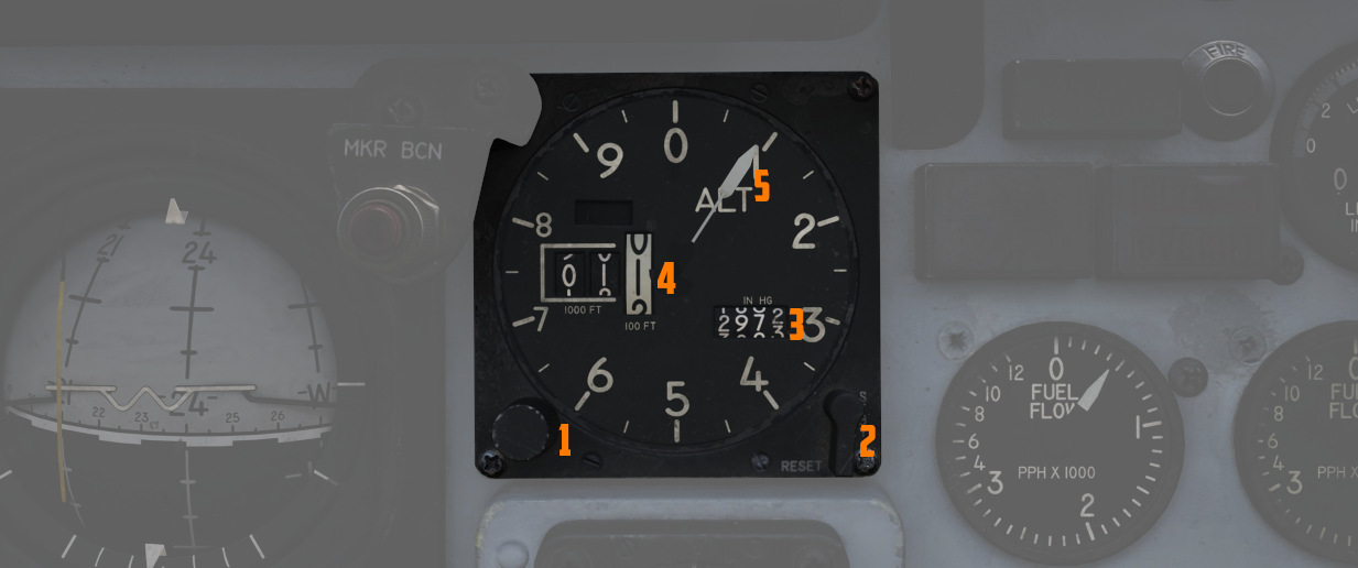
A counter-pointer style altimeter, with thousandths in the counter window (
Vertical Velocity Indicator
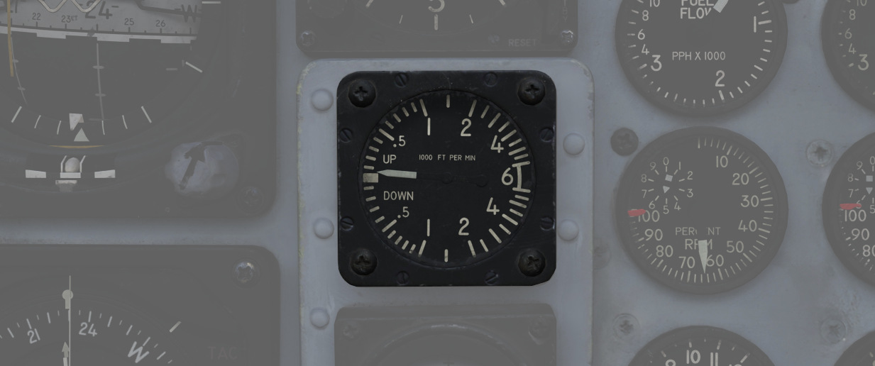
Provides the rate of climb or descent via the static pressure system referenced in thousands of feet per minute.
Standby Attitude Indicator
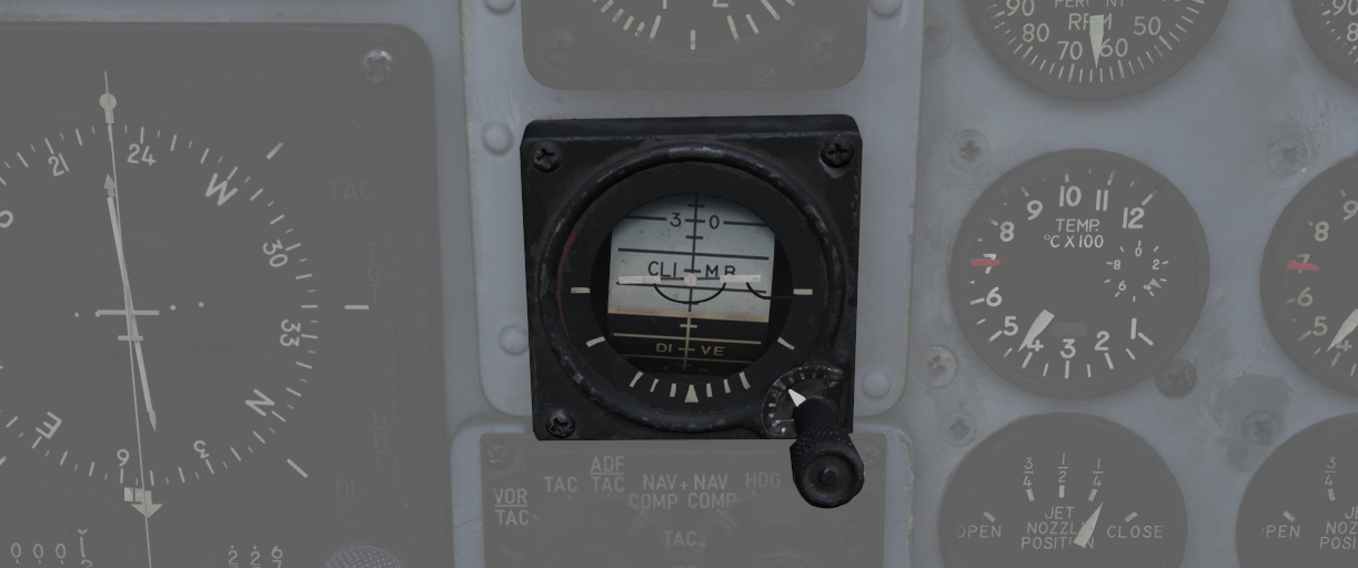
The SAI functions independent of the Flight Director Group, providing reasonably accurate readings (within six degrees) for 9 minutes if power to the system is lost and the OFF flag is in view. Pitch markings are indicated every 5 degrees, while roll markings are in gradations of 10 degrees. Roll is illustrated through 360 degrees, while pitch is limited by stops at 92 degrees in climb and 78 degrees in dive to prevent gimbal lock. The SAI can be unlocked by pressing the knob and trimmed by turning it.
Navigation Function Selector Panel
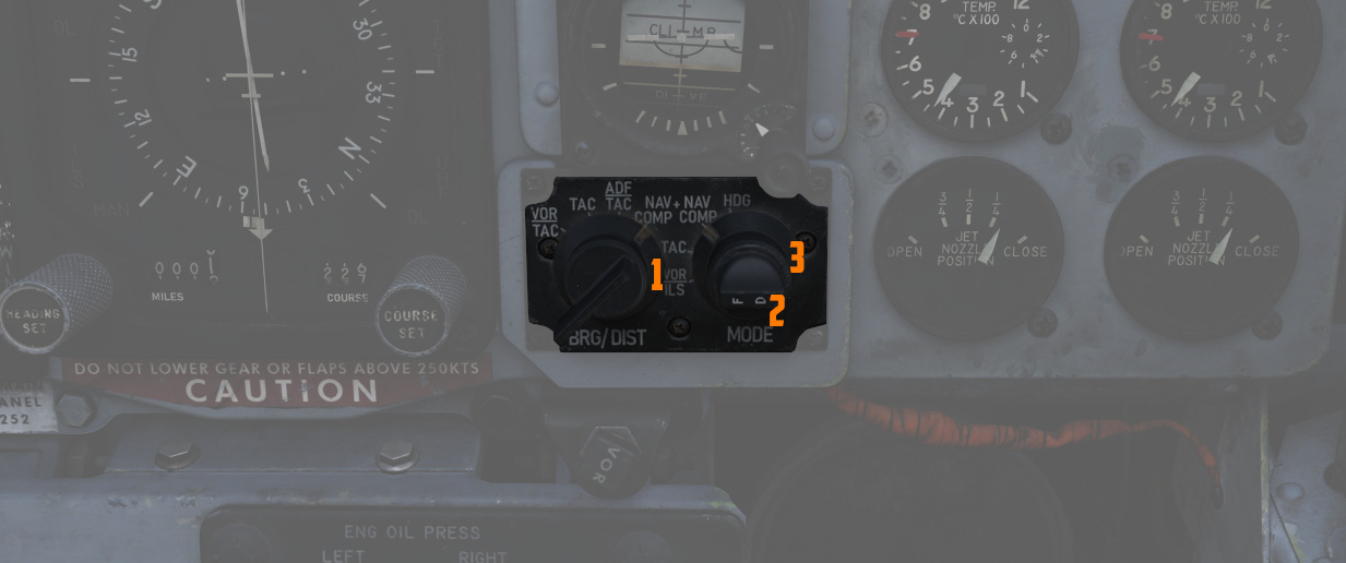
Controls display presentation on the ADI and HDI based on the selected values on
the two knobs; to the left is the Bearing/Distance Knob (
Bearing/Distance Knob
| Name | Description |
|---|---|
| VOR/TAC | Magnetic and relative bearing to VOR station and TACAN range displayed on HSI. |
| TAC | Magnetic and relative bearing and range to TACAN station displayed on the HSI. |
| ADF/TAC | Magnetic and relative bearing to ADF station and TACAN range displayed on HSI. |
| NAV COMP | Magnetic and relative bearing and range provided from navigation computer (i.e. waypoints) on HSI. |
Mode Selector Knob Display Functions
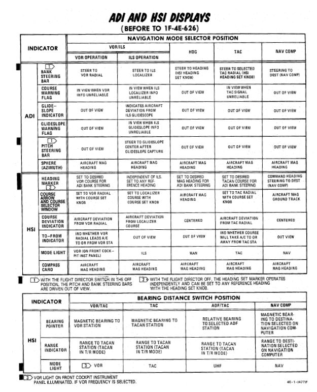
VOR Lamp

Illuminates to indicate that the VOR system is ready and receiving.
That is, a valid VOR frequency has been selected, a signal is received and the navigation knobs have been turned to VOR navigation.