Front Section
Intercom Control Panel
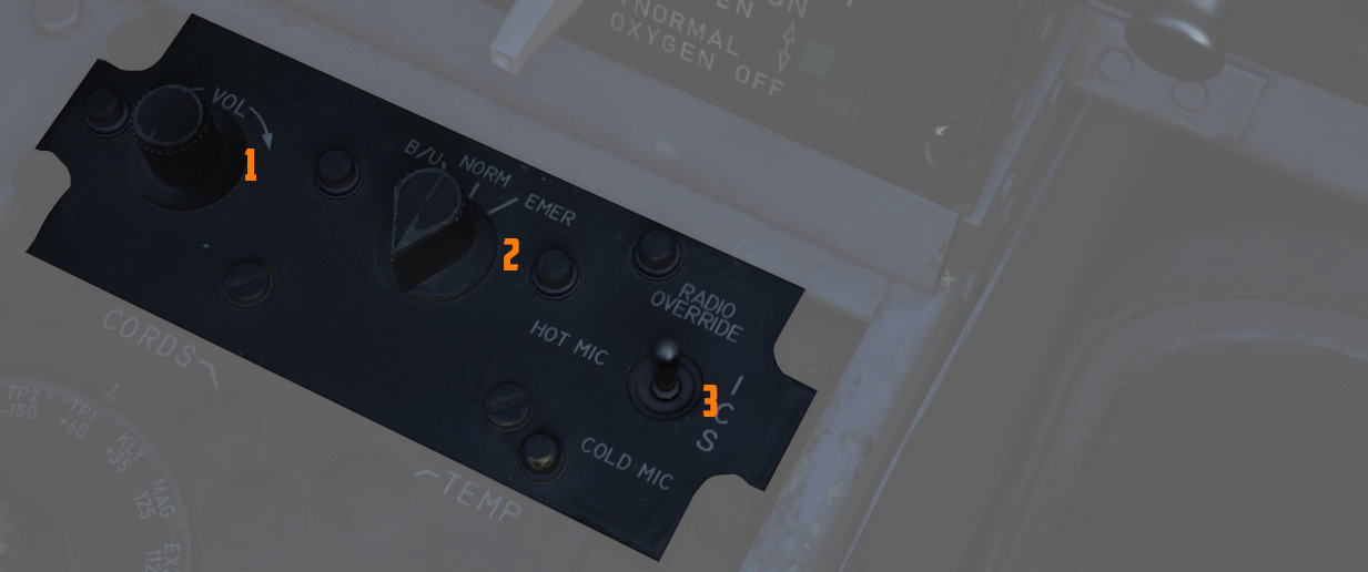
Volume Control Knob
Turned clockwise (
Function Selector Switch
A three position switch (
| Name | Description |
|---|---|
| COLD MIC | Mic switch on throttle must be held to activate intercom. |
| HOT MIC | Voice automatically transmitted on intercom. |
| RADIO OVERRIDE | Voice automatically transmitted on intercom. All volumes but Shrike tone and Stall Warning are reduced in volume. |
Amplifier Select Knob
Determines current amplifier (
| Name | Description |
|---|---|
| B/U | Backup headset amplifier provides audio. |
| NORM | Primary headset amplifier provides audio. |
| EMER | Uses the amplifier from opposite cockpit; all and only audio including radio received to that cockpit is heard. |
Control Monitor Panel
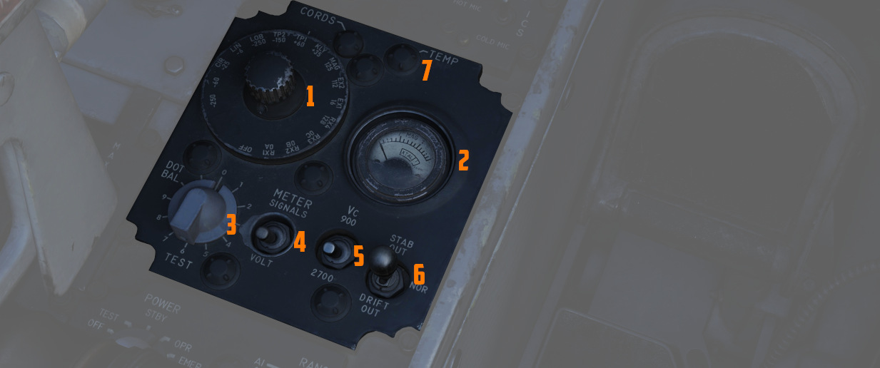
Tests and monitors the APQ-120 Radar.
Cords Light
Not used in the F-4E.
Temp Light
Illuminates (
Meter Selector Knob
A sixteen position rotary knob (
Monitor Meter
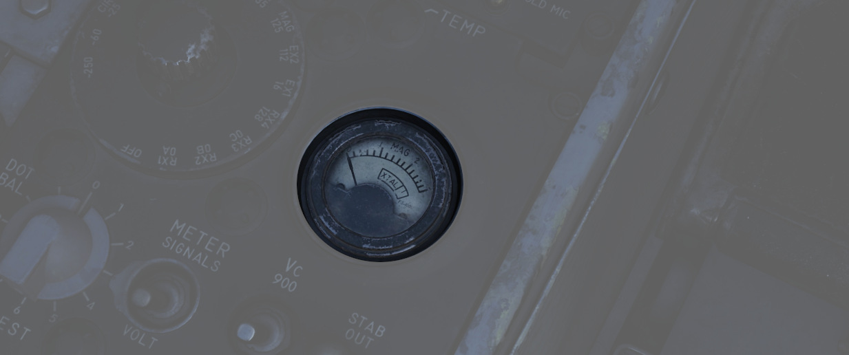
Provides voltage, current, and signal indications (
Test Knob
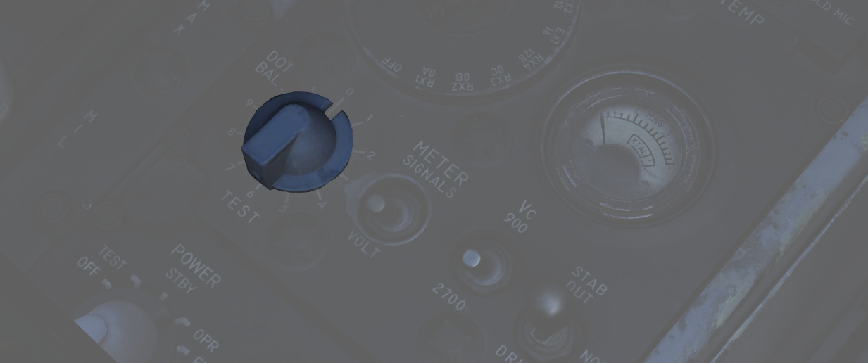
An eleven position rotary knob (
| Name | Description |
|---|---|
| 0 | Displays standard B scope presentation to confirm all elements are functioning correctly. |
| 1 | Confirms break lock timing delay, AIM-7 tuning status, and Range lamp status function. |
| 2 | Confirms proper AIM-7 head position aim and SHORT pulse function against two targets. |
| 3 | Confirms angle tracking performance against a locked target that rotates inside ASE circle. |
| 4 | Used while lock is achieved in another mode, confirms HOJ and AOJ functionality. |
| 5 | Checks range rate, lead angle, CAA, and PLMS function. |
| 6 | Confirms proper AIM-7 attack display and interlock function. |
| 7 | not available |
| 8 | not available |
| 9 | not available |
| 10 | not available |
| DOT BAL | Confirms AIM dot centering calibration. Also used for TIRS data transfer. |
Meter Switch
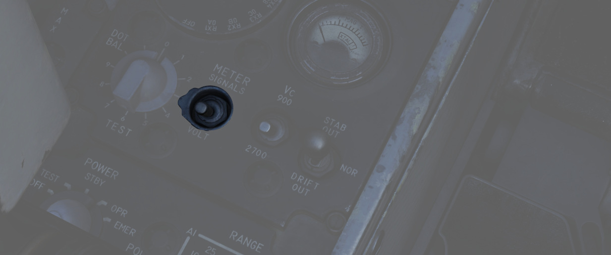
A two position switch (
Vc Switch
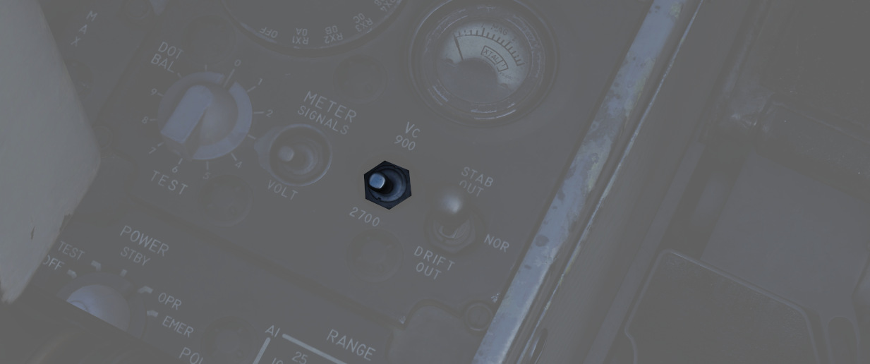
A two-position switch (
Stab Switch
A three position switch (
| Name | Description |
|---|---|
| NOR | Normal operation; inputs of pitch and roll are fed to the antenna stabilization circuit. |
| STAB OUT | Horizon line removed from scopes and stabilization drift servos are zeroed. |
| DRIFT OUT | INS drift compensation is removed; antenna uses direct pitch and roll input tracking. |