Front Section
The front section of the left console houses the oxygen panel, throttle and engine-related controls.
Left Utility Panel
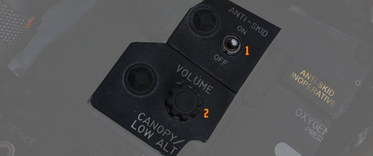
Anti-Skid Switch
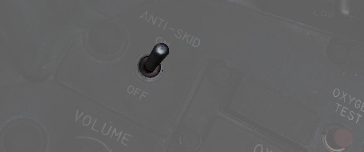
A two position switch (
Anti-Skid Inoperative Light
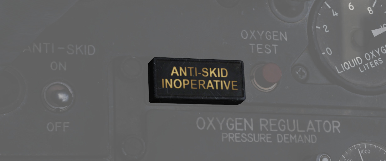
Illuminates when the Anti-Skid Switch is set to OFF, the Emergency Quick Release Lever is pressed, or there is an issue with the Anti-Skid System.
Canopy/Low Altitude Warning Volume
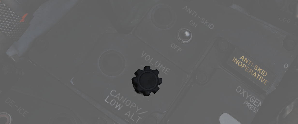
A rotary dial (
This system is not installed on this variant of the F-4E.
Oxygen Regulator and Oxygen Quantity Gauge
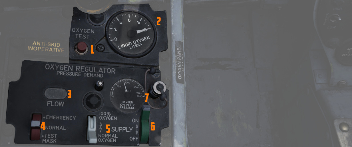
Supply Lever
Two-position switch (
Diluter Lever
A two position (
For a proportional amount of air to oxygen, the NORMAL OXYGEN position should be selected.
For pure oxygen, the 100% OXYGEN position should be selected. This setting is preferable if fire, toxic smoke or fumes occur in the cockpit.
Emergency Lever
Three-position switch (
The lever should remain in the center (NORMAL) position at all times, unless an unscheduled pressure increase is required.
Flow Indicator
Alternates between black and white (
Oxygen Pressure Gauge
The oxygen pressure gauge (
For further information, see 3.7 Utility chapter, Oxygen section.
Oxygen Quantity Gauge
The oxygen quantity gauge (
Oxygen Quantity Test Button
The button (
With the button pressed, both gauge needles should move to an indication of zero.
As the needle in the front cockpit passes through the 1 liter indication, the OXYGEN LOW warning light on the front telelight panel should illuminate, and remain illuminated until the button is released and the needle moves above 1 liter again.
Forward Hand Control
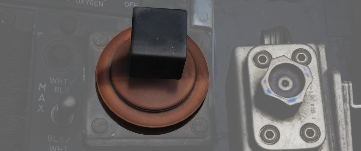
Small joystick enabling the Pilot to control and steer guided Weapons such as Mavericks or Bullpups.
Outboard Engine Control Panel
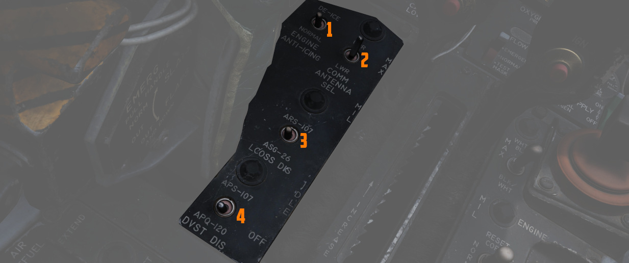
Engine Anti-Icing Switch
Two position switch (
The system should only be used below high-mach numbers. At high-mach speeds, the compressor inlet temperature is enough to prevent ice from building up.
Communications Antenna Select Switch
Two position switch (
The Upper position should be used for take-off and landing since the lower antenna could interfere with the anti-skid wheel speed sensor and thus create a malfunction in the anti-skid system. The lower antenna could also interfere with the nose gear steering whilst transmitting. This happens due to electromagnetic interference radiating from the lower UHF antenna.
LCOSS Switch
A two position switch (
- ARS-107, an older RWR system
- ASG-26, the F-4Es original gunsight system
The switch is a leftover and was only used on aircraft equipped with the APS-107 RWR system.
DVST Switch
A two-position switch (
- APS-107, an older RWR system
- APQ-120, the radar system
The switch is a leftover and not connected on aircraft equipped with the DSCG instead of the previous DVST screen.
Inboard Engine Control Panel
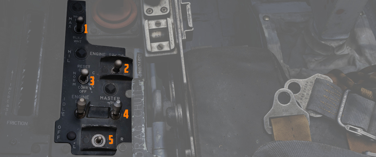
The Inboard Engine Control Panel carries the following controls:
Target Contrast Switch
The three position switch (
| Name | Description |
|---|---|
| WHT/BLK | Programs the missile seeker to track a light target on a dark background. |
| AUTO | Programs the missile to use its automatic tracking mode. |
| BLK/WHT | Programs the missile seeker to track a dark target on a light background. |
💡 This does not change the polarity of the video but the coding of the seeker itself.
Engine Start Switch
Three position switch (
CADC Static Pressure Compensator Correction Switch
Three-position switch (
| Name | Description |
|---|---|
| RESET CORR | Actuated after engine startup, then in flight if a SPC warning is caused by transient conditions. |
| NORM | Regular operating position of switch upon release of RESET CORR or actuation out of CORR OFF. |
| CORR OFF | Manually disengages SPC altitude lag compensation. |
Engine Master Switches
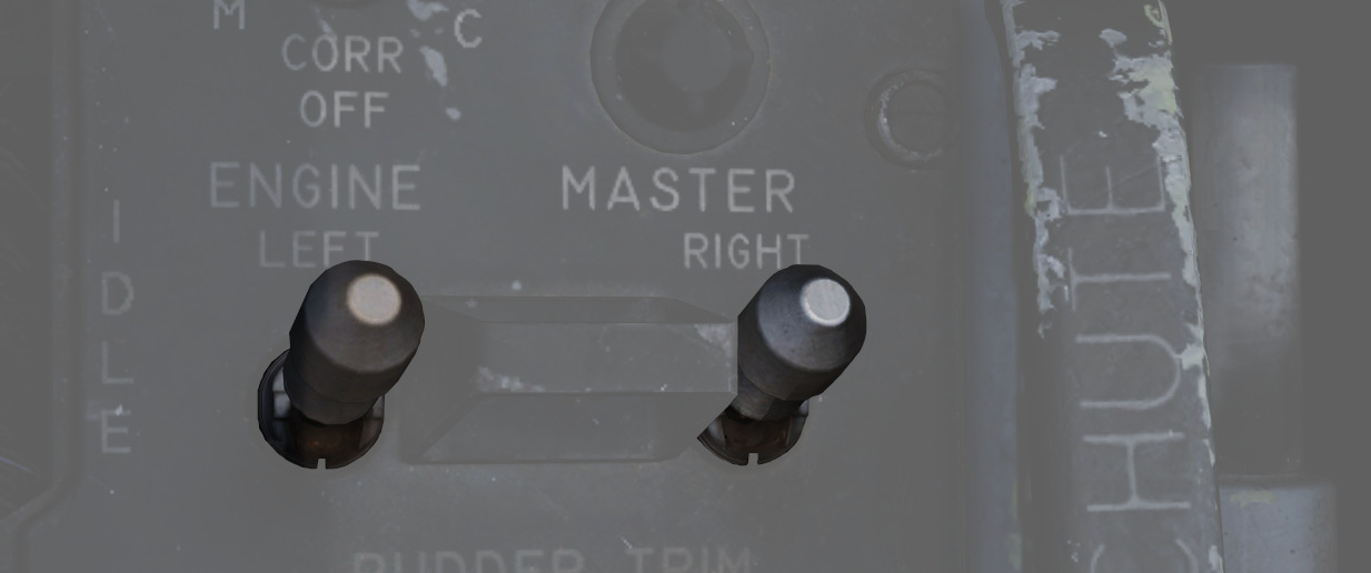
A pair of two-position lever lock switches (
Rudder Trim Switch
A three position switch with automatic return to center (
Throttles
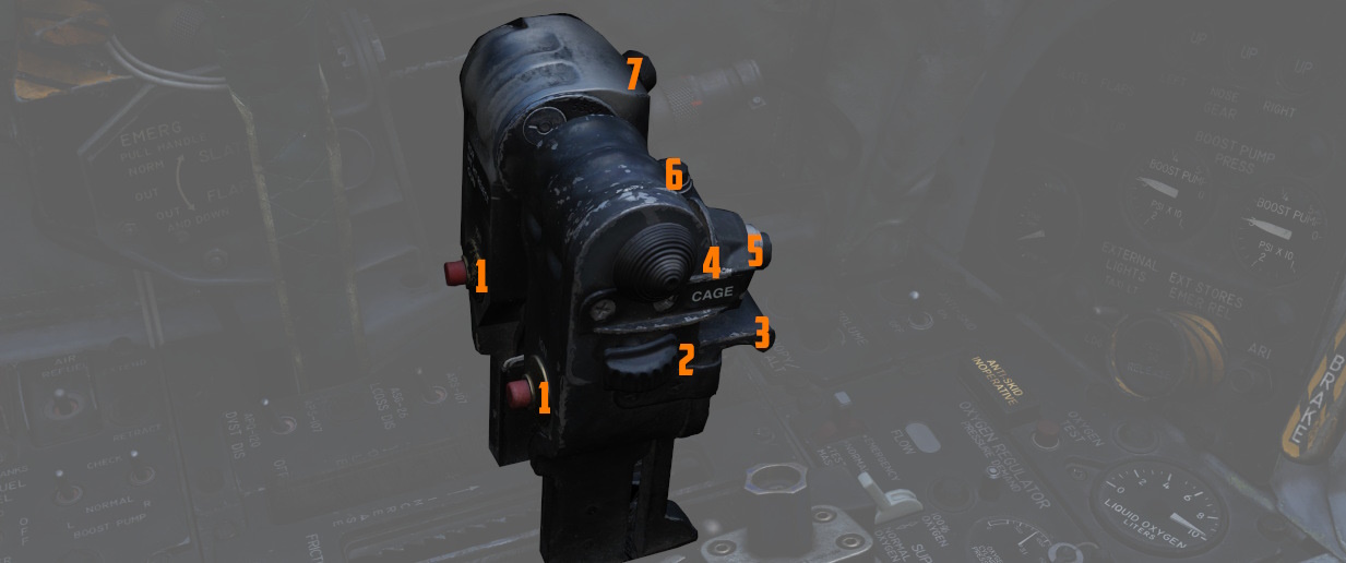
The throttle arrangement for each engine in the F-4E Phantom II is located on the front and rear cockpit left console. Mechanical linkage transmits throttle movement to the engine fuel control. A friction-adjusting lever allows customization of throttle friction. Afterburner initiation occurs by shifting the throttles outboard and moving forward from the MIL position. The Afterburner gate can be adjusted in the special options of the module.
Throttle movement is smooth and continuous, with afterburner modulation possible throughout the range. Moving the throttles from IDLE to OFF closes the fuel shutoff valve, stopping fuel flow. To transition from OFF to IDLE or MIL, advance the throttles straight forward. Shifting the throttles outboard allows movement from MIL to MAX, enabling forward motion in the afterburner range. For further information see 3.1.2 Engines chapter.
Fingerlifts
Front cockpit throttles feature finger lifts (
Ignition Buttons
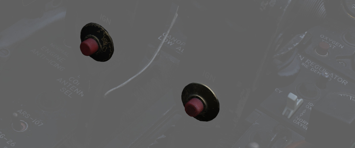
Engine ignition for startup is performed using a pair of spark plugs on each
engine, activated by pressing the red Ignition Button (
Cage Button
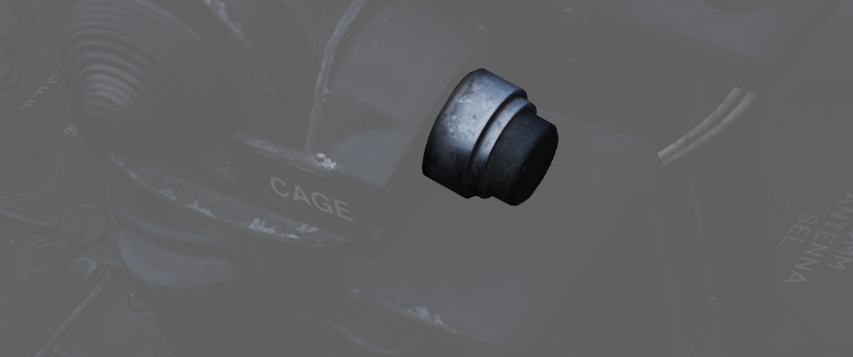
A spring-loaded button (
Dispense Button
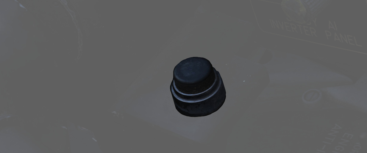
When pressing the dispense button (
Speed Brake
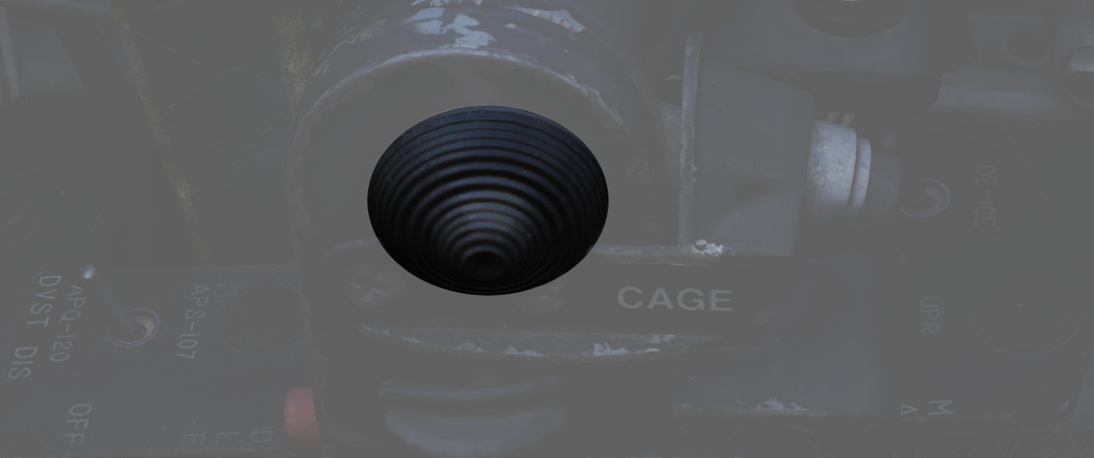
The Speed Brakes are actuated by a three-position switch (
Mic Switch
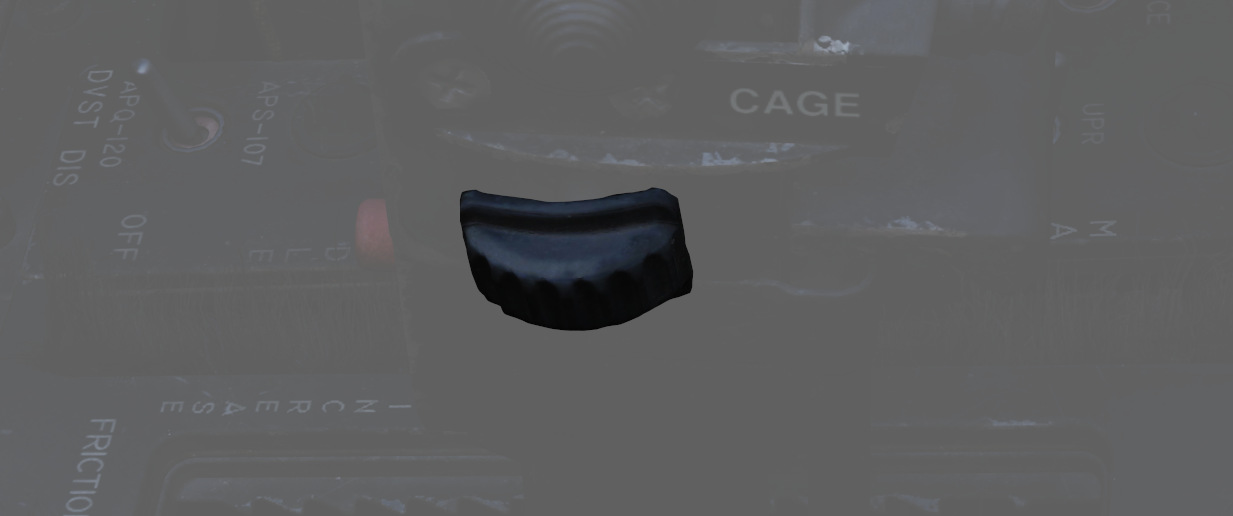
The microphone switch (
Pinky Switch
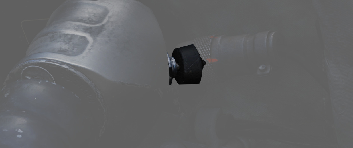
The guns/missile (pinky switch) is a four-position switch (