Right Wall
The right wall features the main circuit breakers and lighting controls.
Canopy Manual Unlock Handle
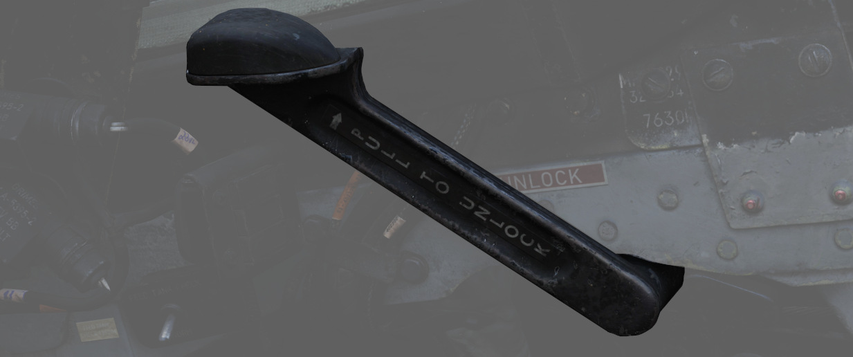
The manual unlock handle is used in the event of pneumatic system failure.
The handle, when pulled aft, unlocks the canopy so that it may be pushed open. Before manual unlocking of the canopy, the normal control lever must be placed in the OPEN position.
For normal operation, the handle should be left in the forward position.
If the canopy is not properly locked, the CANOPY UNLOCKED warning light on the telelight panel illuminates.
Flight Instrument Lights Intensity Panel
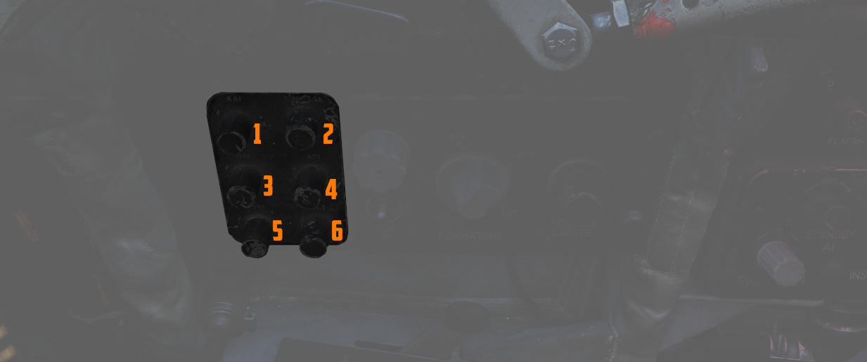
The Instrument Lights Intensity Panel has six knobs that allow to independently change illumination intensity on the following indicators for both cockpits:
- Airspeed/Mach Indicator (
2 ) - Attitude Director Indicator (
4 ) - Angle of Attack Indicator (
1 ) - Vertical Velocity Indicator ((
5 )) - Altimeter (
6 ) - Horizontal Situation Indicator (
3 )
The base intensity of all indicators is controlled with the Flight Instrument Light knob.
🚧 These knobs will be made available later during Early-Access.
Formation and Indexer Lights Control Panel
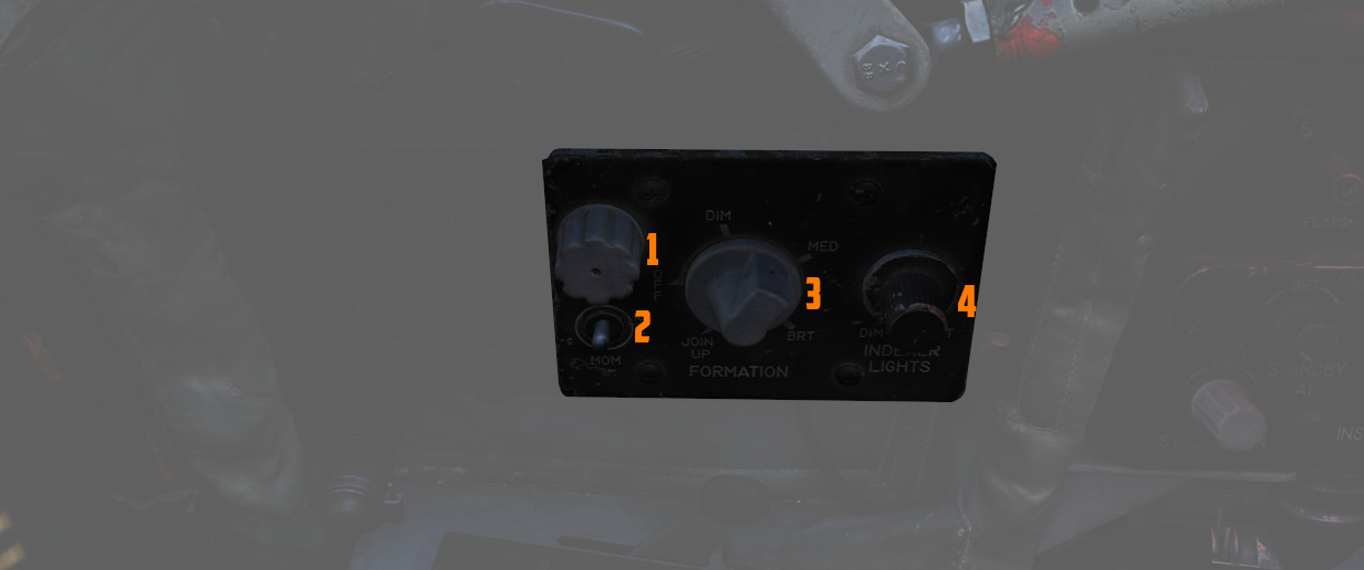
Control of the formation lights, which are found on the wing tips, both sides of
the vertical stabilizer, and along the fuselage forward and amidship, is
performed using the three position switch (
Also on this panel is the Indexer Lights brightness knob (
The fuze cap (
For further information on the lighting, see the 3.9 Lighting chapter.
Circuit Breaker Panel
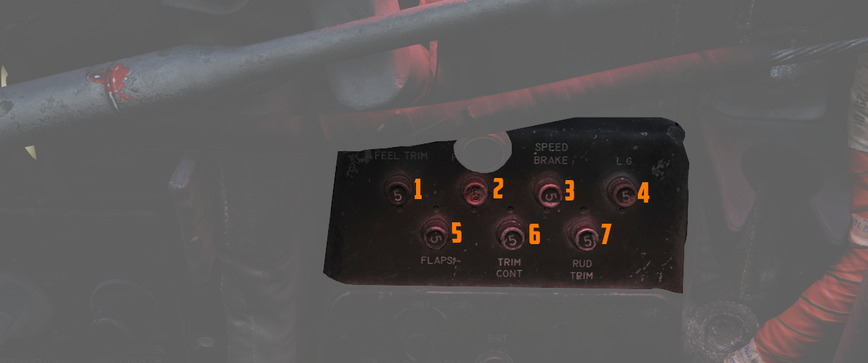
Contains seven circuit breakers responsible for flight control surfaces and other systems important for the safe operation of the aircraft.
- AIL Feel-Trim (
1 ) - STAB Feel-Trim (
2 ) - Speed Brake (
3 ) - Landing Gear (
4 ) - Flaps (
5 ) - Trim Controls (
6 ) - Rudder Trim (
7 )
If a circuit breaker is popped, the corresponding system does not receive power and cannot be operated anymore.
Emergency Floodlights Panel
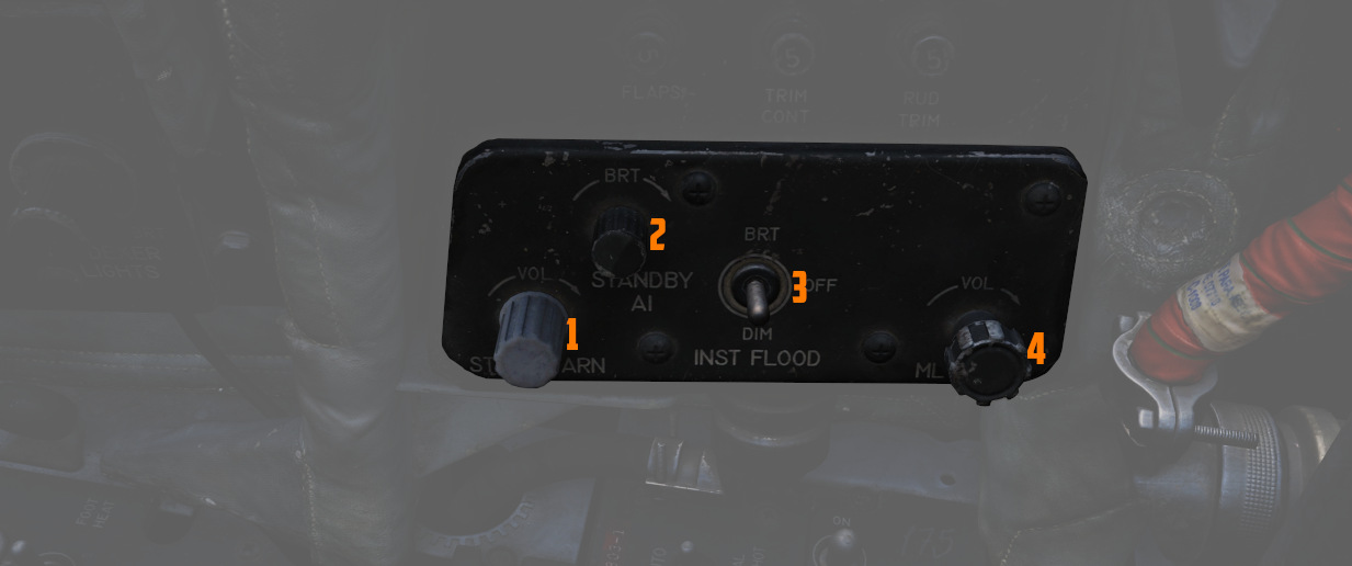
This auxiliary panel has various controls for lights and also audio.
Stall Warning
The Stall Warning knob (
Under certain conditions, the system can override the volume to ensure the cue is always audible in dangerous situations.
Standby AI
This knob (
Instrument Flood
The three position switch (
For further information on the lighting, see the 3.9 Lighting chapter.
ML Audio
This knob (