Weapon Management
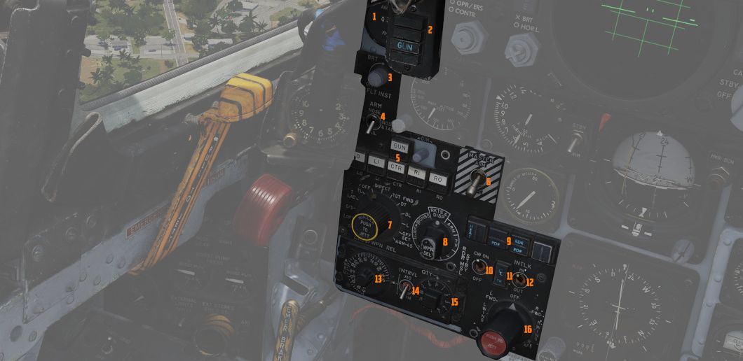
This group on the left area of the main panel provides all weapon-related
settings, such as arming missiles or selecting the bomb delivery mode. It
features a true airspeed indicator (
Range Indicator
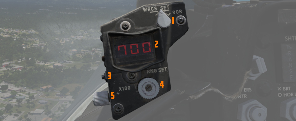
This panel provides the pilot with a readout of the slant range measured by the Pave Spike Targeting Pod (x100 ft).
When the Test-Button (
The Mode-Knob (
- WRCS - Automatic Delivery
- ROR - Release on Range
In the SET position, the display shows the desired release range used in the ROR
mode. The knob below the readout (
Head Up Display Indicators
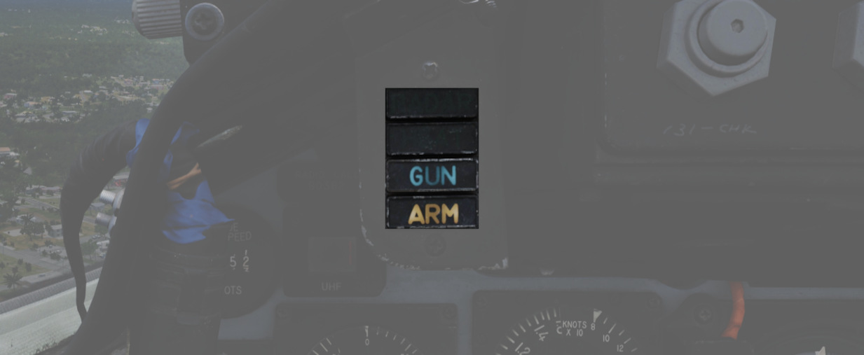
The Head Up Display indicator panel provides weapon status for the Master Arm control, as well as the current selected air-to-air weapon, based on the position of the pinky switch on the left throttle handle.
| Name | Description |
|---|---|
| RADAR | Illuminates when a radar-guided air-to-air missile is selected. |
| HEAT | Illuminates when an IR-guided air-to-air missile is selected. |
| GUN | Illuminates when the nose gun is selected. |
| ARM | Illuminates when the Master Arm switch is selected to ARM. |
UHF Remote Channel Indicator
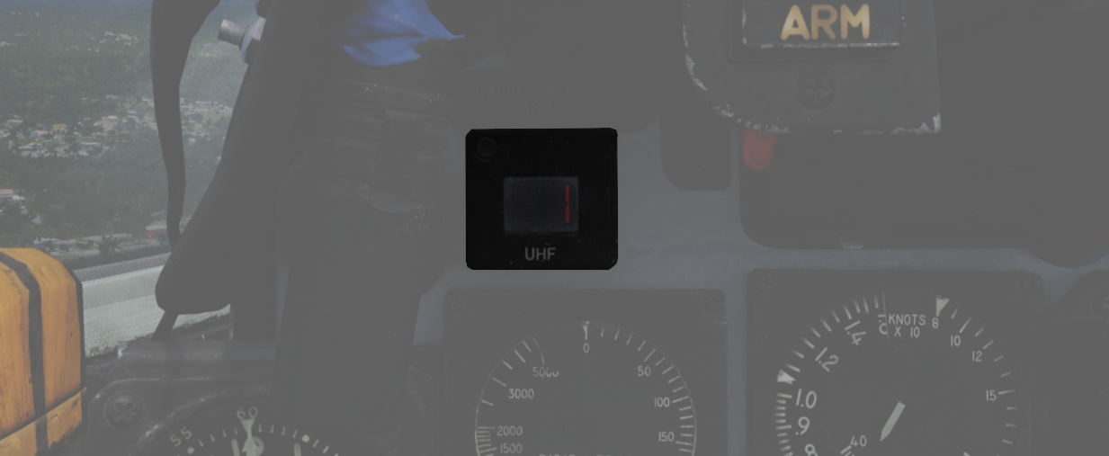
Provides the current selected channel value when the radio is set to PRESET. Otherwise, the indicator displays M if the radio is set to Manual, G when the COMM function is set as GUARD/ADF, or A when the A-3-2-T switch is in A.
True Airspeed Indicator
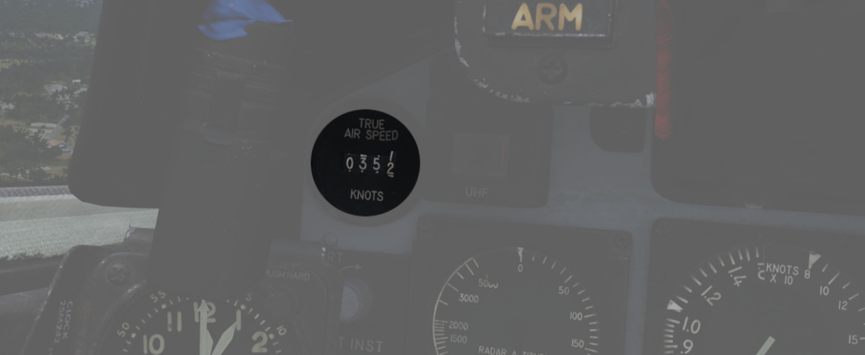
Provides the aircraft's true Airspeed in knots, and is calibrated from 150 to 1500 knots; airspeeds below this range are thus not reliable.
Flight Instrument Brightness Knob
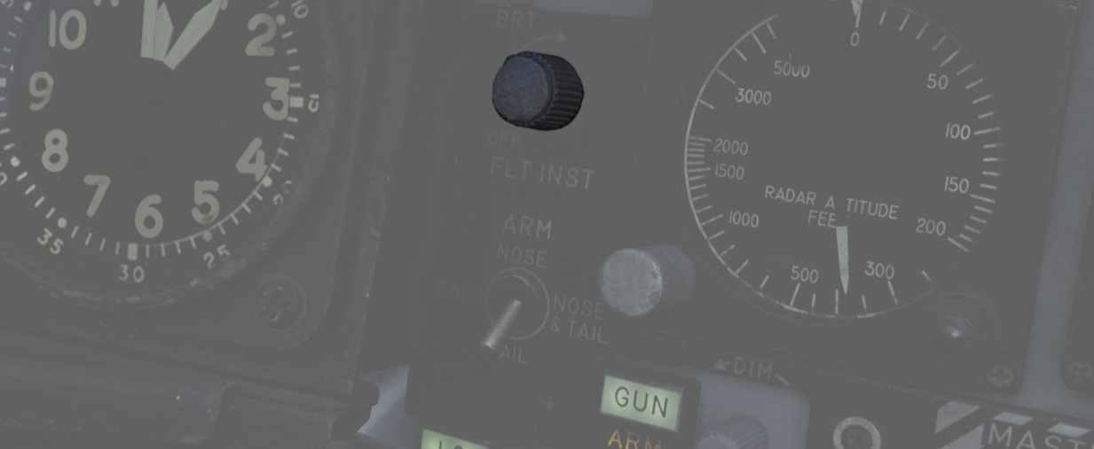
Controls edge lighting of the main flight instruments of both cockpits.
Rotating clockwise will increase their brightness, but at the same time also dim most warning and indication lamps in the aircraft.
💡 When dimmed, SHOOT lamps are turned off entirely.
Flight instrument lights can additionally be controlled individually with knobs on the Flight Instrument Lights Intensity Panel, located on the right wall.
See 3.9. Interior Lighting for details.
🚧 The flight instrument lighting is currently linked to the Instrument Panel Knob on the right console instead. The correct controls will be made available later during Early-Access.
Nose/Tail Arming Switch
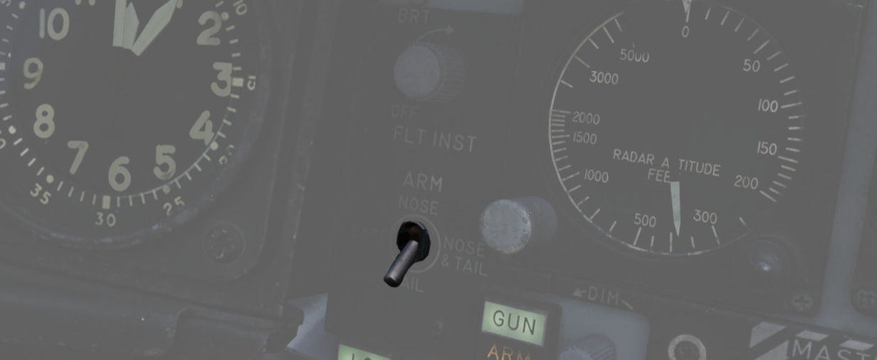
Controls the arming solenoids of the MER and TER racks, selecting what MER/TER position(s) arming lanyards are pulled from released bomb fuzes upon separation, thus making them live. This function also controls selective low/high drag capability for retarded bombs.
| Name | Description |
|---|---|
| SAFE | No arming solenoids activate; bombs release without fuzing enabled. |
| NOSE | Forward and center position solenoids activate to hold arming lanyards. |
| TAIL | Aft position solenoids activate to hold arming lanyards. |
| NOSE/TAIL | Forward, center, and aft position solenoids all activate to hold arming lanyards. |
For example, MK-82 Air or Snakeye variants will only detonate if the nose fuze is selected and switch between high drag configuration with the tail fuze set and low drag if not set.
Station Select Buttons
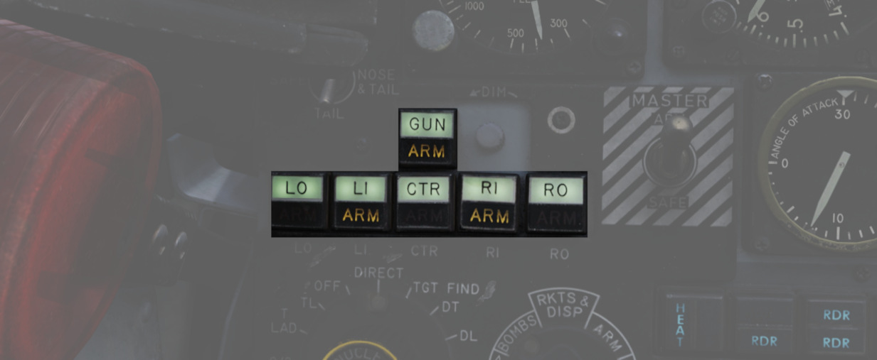
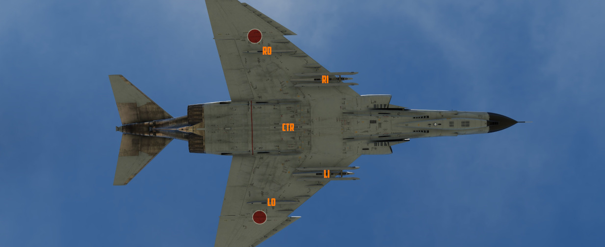
The Station Select Buttons are used to activate air-to-ground munition stations and the nose gun. Upon selection of a station, the upper half denoting the position will illuminate green to confirm the station is active. The lower half will illuminate amber once the necessary mode is selected, the weapon is compatible with the weapon select knob option, the Master Arm is in the ARM position, and any necessary warm up period for the selected weapon type is completed. L and R positions are left and right, respectively, with O denoting outboard and I denoting inboard stations. The centerline weapon position is CL, and the nose gun is armed with the GUN station selector button.
Dimmer Knob
A dimmer knob is also provided to raise or lower the lighting of the station select buttons relative to the current cockpit conditions.
If the Flight Instrument Brightness Knob above it is set to the full CCW position, it overrides the dimmer knob and Station Select Buttons are always illuminated at full brightness.
💡 The dimmer knob can control brightness only within a limited range.
Master Arm Switch
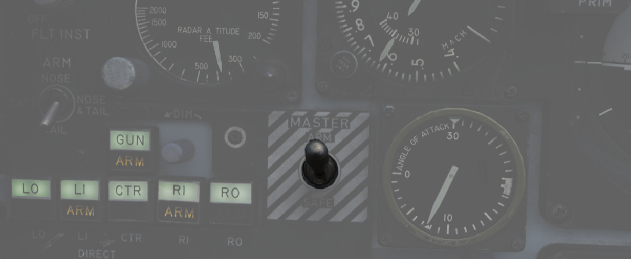
Provides master arming function for all aircraft weapons.
Delivery Mode Knob
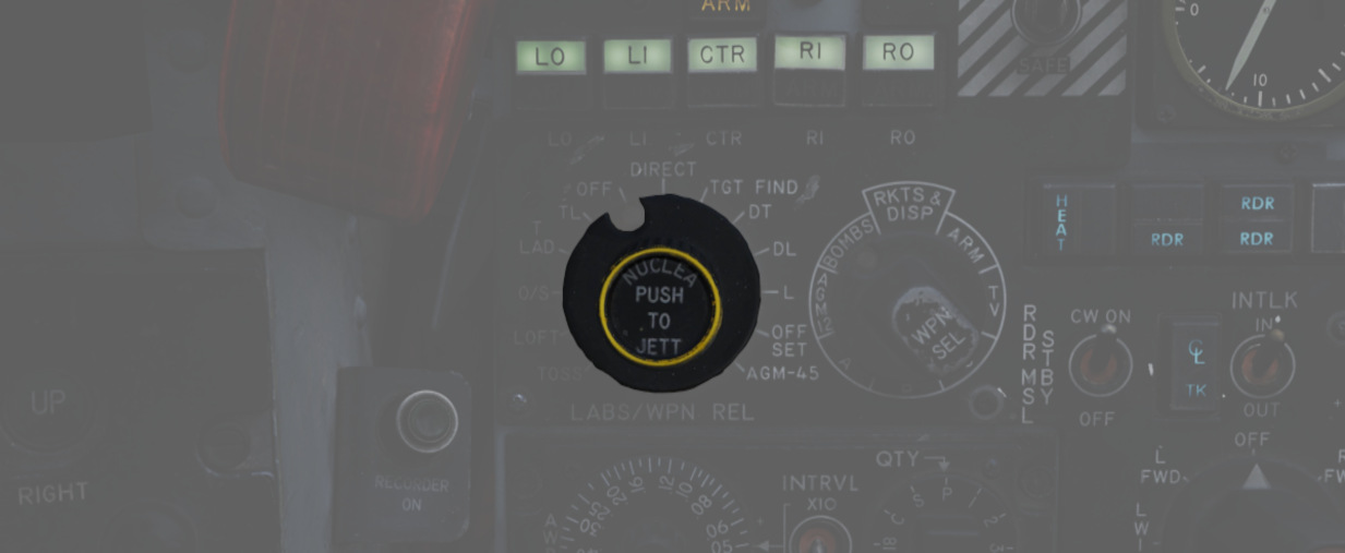
The Delivery Mode Knob sets the fire control system to the desired air to ground weapon release type. Split into two halves, the left side of the dial references ARBCS (Altitude Reference and Bombing Computer Set) delivery modes, while the right side provides automated release functions using the WRCS (Weapon Release Computer Set) with the possible tie-in to the navigation computer, depending on mode. At the 11 o'clock position is the OFF position, which is utilized for air-to-air weapons (including the gun). The next mode, DIRECT, is used for video-directed weapons such as the AGM-65 and as a direct delivery bombing mode. The full series of positions is as follows, clockwise from the left:
| Name | Description |
|---|---|
| INST O/S | Instantaneous Over the Shoulder |
| LOFT | Loft |
| O/S | (Timed) Over the Shoulder |
| T LAD | Timed LADD (Low Angle Drogue Delivery) |
| TL | Timed Level |
| OFF | Off (Air-to-Air) |
| DIRECT | Manual Direct |
| TGT FIND | Target Find (Nav mode and Pave Spike only) |
| DT | Dive Toss |
| DL | Dive Laydown |
| L | Laydown |
| OFF SET | Offset Bomb |
| AGM-45 | AGM-45 Shrike |
For further information, see 4.3 Air-to-Ground weaponry chapter.
Weapon Selector Knob
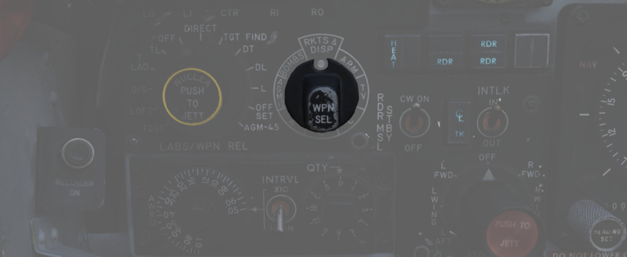
Used to select the appropriate type of weapon, providing release signals to the AWRU (Aircraft Weapons Release Unit). ARM and TV positions inhibit air-to-air weapon firing unless a CAGE signal is active. ARM and TV positions do not affect the tuning status of radar-guided weapons. Positions are as follows:
| Name | Description |
|---|---|
| AGM-12 | AGM-12 Bullpup |
| BOMBS | Bombs (all types including CBUs). |
| RKTS & DISP | Rockets and dispensers. |
| ARM | Anti-Radiation Missile (AGM-45 Shrike). |
| TV | Electro-optical weapons (AGM-65 Maverick). |
| C | Not used; may be utilized as an OFF position. |
| B | Like AIR TO AIR switch in rear cockpit, cancels CAGE requirement. |
| A | Backup mode that simultaneously releases CBUs, rockets, or dispensers; bombs do not release. |
Aircraft Weapons Release Unit
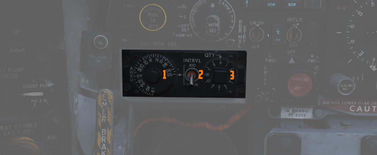
Provides timed interval release scheduling of single or multiple bombs or rockets and dispensed munitions based on the selections made between the interval knob, the QTY (quantity) knob and the INTRVL switch.
For further information, see 3.11.2 Aircraft Weapons release unit (AWRU).
Interval Knob
The interval knob (
Interval Switch
The INTRVL switch (
Quantity Knob
The quantity knob (
Selecting "1" places the AWRU into single manual bombing mode; one push of the bomb release button releases one bomb.
Selecting a value from "2" to "18" sets the AWRU into single ripple mode; in this mode, the AWRU will release bombs according to the programmed interval until the set number of rounds is dropped, or the bomb button is released. Upon release, the count is reset, and a subsequent press and hold will drop the programmed number of bombs.
Selecting "C" sets the AWRU into single continuous mode; pressing the bomb release button drops rounds according to the programmed interval until the bomb button is released, or all munitions from the selected pylons are expended.
The "P" setting is for pairs manual mode. With at least two stations selected, each push of the bomb button will release two bombs. Like single manual mode, this does not include an interval function.
Lastly, the "S" setting, for salvo, releases bombs in accordance with the chosen interval from all selected stations simultaneously, until the bomb button is released. Ergo, if four stations are selected with a 2-second interval (0.2 on the interval dial, X10 INTRVL switch setting), four bombs will be released every two seconds the bomb button is held down.
Missile Status Lights
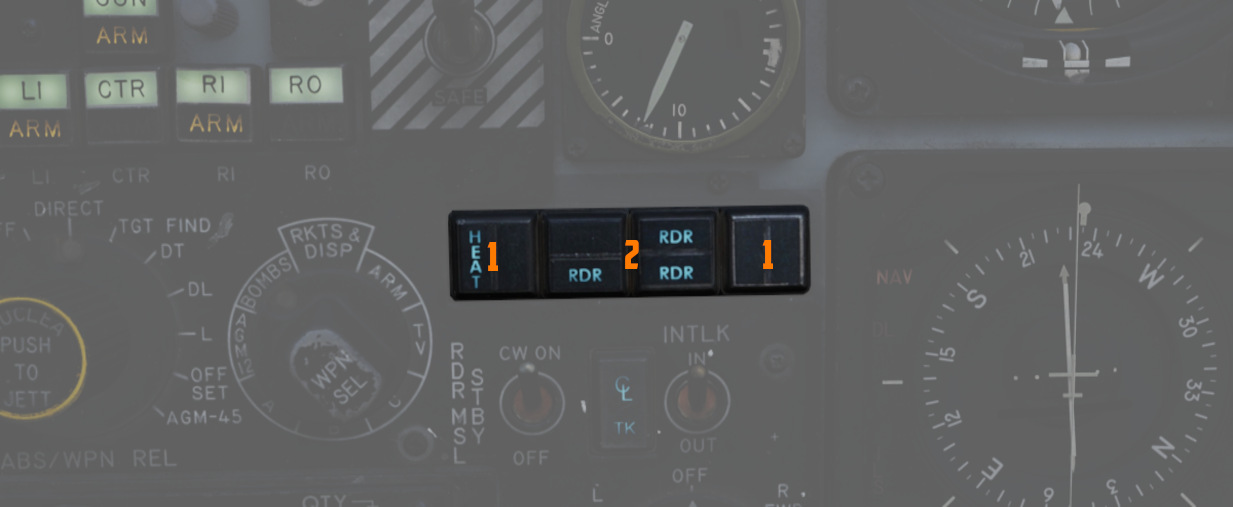
The Missile Status Light window provides confirmation of the currently installed and configured 4.2 air-to-air missiles chapter.
Radar Lights
The RDR lights (
The left pair of lights indicates stations 4 and 3 from top to bottom, while the right pair links to stations 6 and 7, respectively.
Heat Lights
The HEAT lights (
The left pair of lights represents station 2L and 2R respectively, while the right pair is linked to stations 8L and 8R.
Radar Missile Power Switch
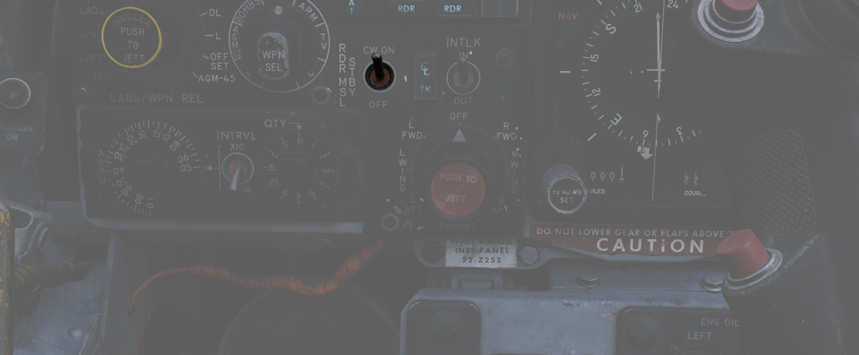
The Radar Missile Power Switch provides power to the klystron continuous wave (CW) emitter responsible for guidance signals. This also powers the Sparrow tuning drive, which is responsible for tuning the Sparrows to the correct continuous wave carrier frequency for guidance.
When the radar power knob is out of the OFF position, power is applied to the circuit 30 seconds after this selection.
The STBY position maintains warmup power to the missiles and continuous wave tuning drive once the missiles have been tuned. This keeps the Sparrows and Tuning Drive warm, but the Sparrows are not tuned.
The CW ON position allows for constant tuning and missile state monitoring with the radar mode not in TV. This also causes the radar klystron to begin continuous wave emission.
Tuning can be performed on the ground with the radar in TEST mode to preclude emissions endangering the ground crew.
Centerline Tank Aboard Light
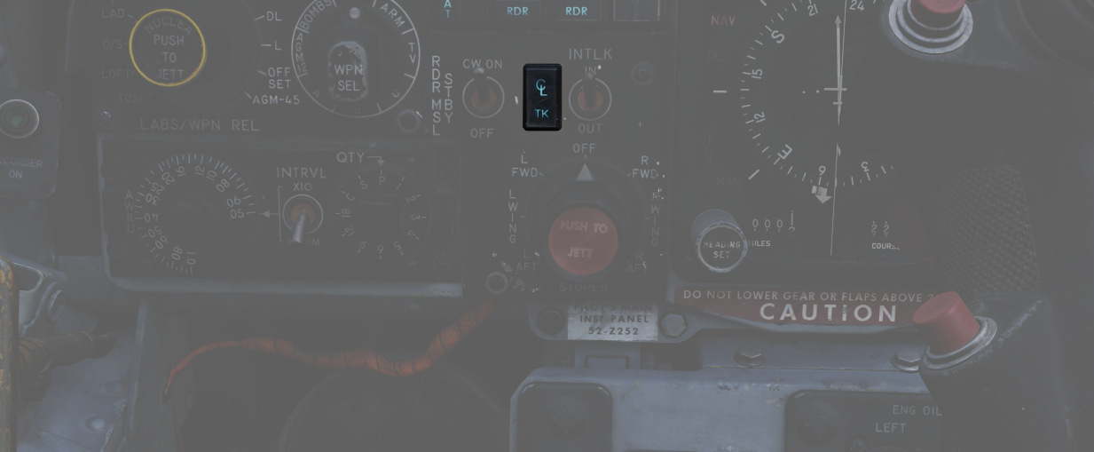
Illuminates when a store's condition exists that precludes the ejection or launch of an AIM-7 missile installed in one of the two forward positions. To use the Sparrows on these stations, the centerline store must be the first to be jettisoned.
See 3.12.1 Multiple Weapons System for details.
Interlock Switch
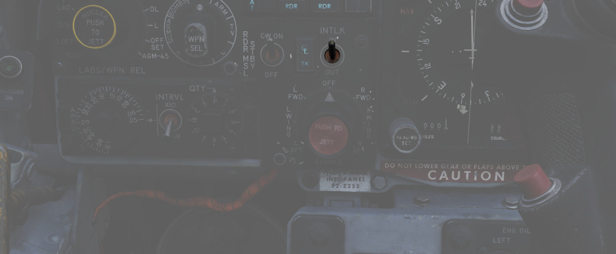
A two-position switch that determines whether the fire control system launch parameter interlocks can prevent an AIM-7 from being launched when the trigger is pulled.
| Name | Description |
|---|---|
| IN | Interlocks engaged; range limits, ASE limits, or radar not in visual intercept inhibits launch. |
| OUT | Interlocks override; AIM-7 will fire when trigger is pulled even when no launch condition is met. |
Selective Jettison Control
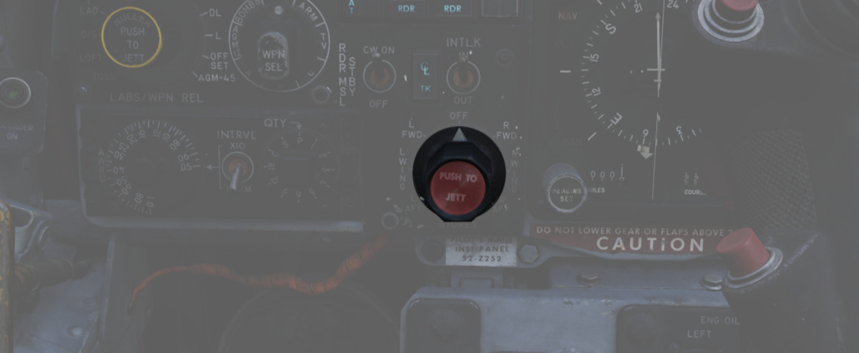
The Selective Jettison Control knob provides the pilot direct access to dump stores on a position-by-position basis.
The pilot selects the desired position by rotating the knob and then presses the button on its front to jettison the selected stores.
| Name | Description |
|---|---|
| OFF | Safes PUSH TO JETT button on the Selective Jettison Control Panel. |
| STORES | Releases all MER/TER, single carried, LAU-88 mounted rounds, or drop tanks currently selected on the station buttons upon PUSH TO JETT. |
| L/R FWD | Jettisons AIM-7 from respective position on PUSH TO JETT. Inhibited if CL TK ON. |
| L/R AFT | Jettisons AIM-7 from respective position on PUSH TO JETT. |
| L/R WING | In conjunction with TV or ARM, jettisons single AGM-65 Maverick or AGM-45 Shrike from wing on PUSH TO JETT. |
For example, to jettison the right and left external fuel tanks, the pilot must select STORES on the knob, press the corresponding station select buttons LO, RO and then push the jettison button.
Recorder Lamp
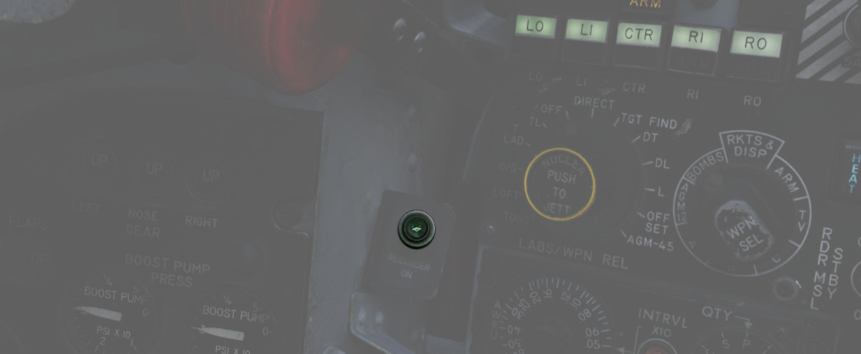
This dimmable lamp is lit to indicate the operation of the Airborne-Video-Tape-Recorder (AVTR).
The AVTR system is controlled by the WSO and records the intercom sound, as well as the rear radar screen.