Aft Section
The aft section of the right console has navigation equipment and controls for exterior lighting.
Compass Control Panel
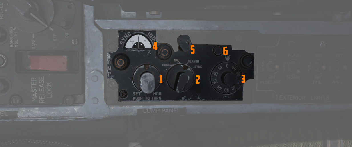
Manages essential controls for the proper operation of the AJB-7 azimuth system. Essential for accurate azimuth output to instruments like ADI, HSI, BDHI, but also to the rear seat attitude indicator, autopilot, and bombing computer.
Mode Selector Knob
Switches (
| Name | Description |
|---|---|
| COMP (Compass) | Used in emergencies when the reference systems fail. Supplies magnetic heading directly from the flux valve |
| DG (Directional Gyro) | Used in extreme latitudes and regions with magnetic distortion, the initial magnetic heading needs manual adjustment. If the reference system is set to STBY, the aircraft's latitude must be adjusted on the latitude knob. |
| Slaved | Primary operational mode under typical conditions, it depends on signals from the flux valve for a gradual synchronization of the system. |
| SYNC | Spring-loaded to return to SLAVED, facilitates fast synchronization between the compass flux valve and azimuth reference. |
Hemisphere Switch and Latitude Control Knob
Adjusted to set the aircraft's hemisphere and latitude in the DG Compass System
mode, when operating with the STBY reference system. The hemisphere is
determined by rotating the screw (
Set Heading Control Knob
Push-to-turn knob (
Sync Indicator
Displays (
Exterior Lights Control Panel
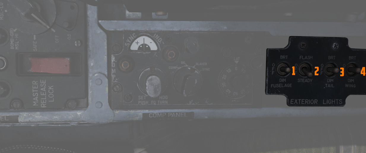
This panel contains controls connected to most of the exterior lighting:
- 3 position lights (green, red, white)
- 2 wingtip join-up lights (green, red)
- 3 fuselage lights (white)
- anti-collision tail light with 2 lamps (red)
Three switches labelled Fuselage, Tail and Wing control the brightness of the lights between BRT (Bright), DIM and OFF.
To ensure lights are available even in case of power failure conditions, the BRT and DIM selections are routed through different buses:
| Lamp | Bus |
|---|---|
| Bright | Right Main 28V DC Bus |
| Dim | Left Main 14V AC Bus |
| Anti-Col 1 | Right Main 14V AC Bus |
| Anti-Col 2 | Left Main 14V AC Bus |
For further information about the lighting, see the 3.9 lighting chapter.
Fuselage Switch
The three position switch (
Additionally, if set to BRT and the Flasher Switch is set to FLASH, both anti-collision lights illuminate.
Tail Switch
The three position switch (
Wing Switch
The three position switch (
Flasher Switch
A three-position switch (
- one of the two anti-collision lamps
- tail position light
- fuselage lights
If set to OFF, the controlled lights are OFF regardless of their respective switches. In the STEADY position, they light up corresponding to the selected brightness. The FLASH position lets the controlled lights phase from the set brightness to a low brightness and back.
Airborne Video Tape Recorder
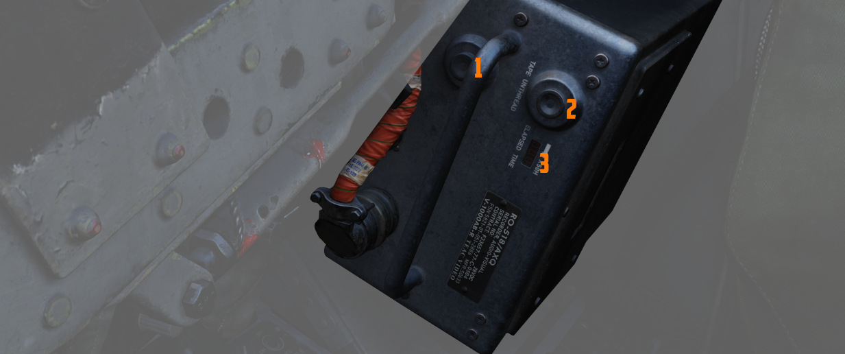
The AVTR system is installed in the rear section to the right of the seat. It is primarily controlled by the WSO and records the intercom sound, as well as the rear radar screen.
Footage is recorded on a standard U-matic S cassette, which can be removed and
replaced using the EJECT Button (
The cassette can record up to 20 minutes, as indicated on the small display
labelled ELAPSED TIME (
See 9.6 DCS Recorders for details on how to access the footage.
💡 Our simulation of the AVTR also doubles as a music player, see Tape Player for details.