Air to Air Radar Operation
Radar operation for Air-To-Air includes the RDR-B and MAP-B modes, along with the BST mode. RDR-B and MAP-B can be used with automatic search and BST mode can be used as a close range mode to cue a target on the boresight.
Automatic Search
During automatic search, the antenna moves back and forth in the radar plane. The limits of this search are determined by the Display Knob. Search is normally 120 degrees wide with the display knob in WIDE positions, and limited to 45 degrees in the NAR position. Only Display Knob positions with B are usable in Air-To-Air operations.
The Radar Mode Knob knob is used to select automatic search by choosing either RDR or MAP. In RDR the number of bars can be selected by the Scan Switch. In MAP only 1 bar is used regardless of the switch. Feedhorn nutation is used with RDR but not MAP; leading to an estimated beam-width of approximately 6.7 degrees in RDR and 3.7 degrees in MAP.
Selecting BST or AIR-GND on the Radar Mode Knob, the antenna scan is boresighted along the radar boresight line.
Below shows the usual symbology present in Automatic Search and Boresight Modes.
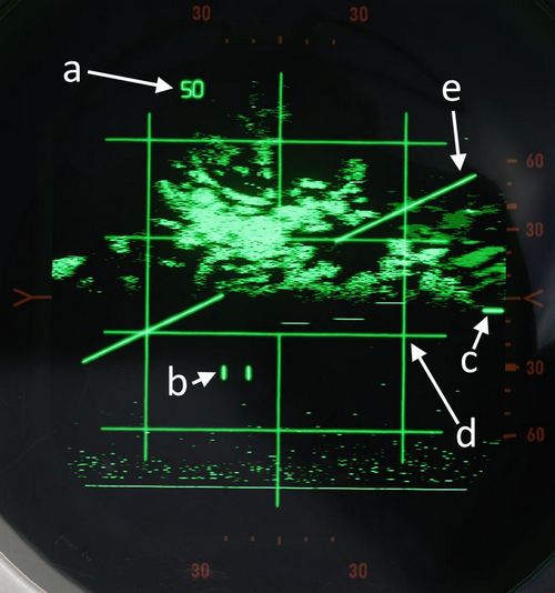
| Item | Name | Description |
|---|---|---|
| a | Range Display | Shows current selected or forced range |
| b | Radar Cursor | The radar cursor is used to select targets and displays the current selected range and azimuth. It is moved by the Antenna Hand Control. |
| c | Antenna Elevation | Shows antenna elevation (in degrees) relative to the radar plane, or aircraft if the Stab Switch is in OUT. This can be moved with the Antenna Hand Control elevation wheel. |
| d | Radar Grid | Left and right vertical lines show 30 degrees left and 30 degrees right. This measurement is relative to the radar plane with the Stab Switch in NOR or DRIFT OUT and relative to the aircraft with the Stab Switch in OUT. Each horizontal line marks a scale where the gaps are 1/5 of the current range setting of the display. |
| e | Horizon Line | Shows the horizon line, only present with Stab Switch in NOR or DRIFT OUT |
Acquisition
Acquisition can be used with any radar mode that uses B-Scope and is used to achieve a tracking condition.
With the Radar Mode Knob in RDR or MAP, Half Action can be held on the Antenna Hand Control trigger to begin acquisition. In RDR or MAP the antenna azimuth will follow the acquisition symbol. In all modes where acquisition can be used the range of the acquisition symbol will set the desired range for lock-on.
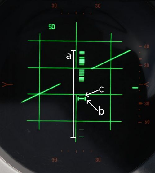
| Item | Name | Description |
|---|---|---|
| a | B-Sweep | The B-Sweep displays the current radar echoes along the azimuth of the antenna, these are displayed in both acquisition and track. |
| b | Acquisition Symbol | Like the radar cursor, the acquisition symbol shows the current selected azimuth and range. It is moved with the Antenna Hand Control. It is also displayed in track to indicate target range and azimuth. |
| c | Target Echo | Target Return displayed along the azimuth |
Track
Automatic tracking can be commanded by first entering acquisition and then, once the target has been bracketed by the acquisition symbol, Full Action can be depressed to enter automatic track.
The type of track entered depends on the selected mode. There are two types of tracking circuits available, angle tracking and range tracking. These will both be described below.
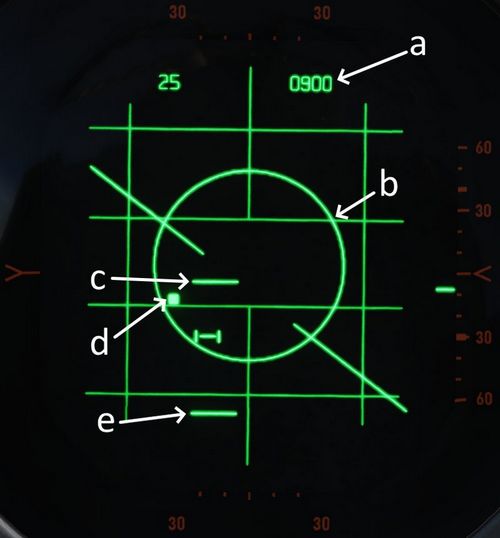
| Item | Name | Description |
|---|---|---|
| a | Display Readout | The readout depends on the position of the Aspect Switch |
| b | Allowable Steering Error | Describes the maximal Off-Angle-Launch-Envelope, see Allowable Steering Error |
| c and e | Range Strobes | Indicates Launch Envelope, see Range Strobes Description |
| d | Aim Dot | Provides pilot steering, see Aim Dot |
On the top right corner of the radar screen is an engraved T symbol which illuminates if a range track condition is present. This is only found on the WSO Screen.
Angle Track
The Angle Tracking circuit steers the antenna to keep the target centered. It does so by making use of feedhorn nutation (conical scan). The antenna steers towards the direction of highest amplitude in the nutation scan pattern. As a result, angle tracking cannot be achieved without nutation (MAP-B begins nutation when using acquisition).
Angle Tracking has two settings set by the Maneuver Switch, HI G and LOW G. These set limits on the acceleration in the angle tracking circuits.
Antenna steering has several important functions:
- Tracking target location in elevation and azimuth
- Providing head aiming angles to the Sparrow for a seeker lock-on.
- Illuminating the target with continuous wave radio frequency energy for Sparrow guidance.
Range Track
The radar uses a range gate to select a target in range. This uses only radar returns within the range gate for its circuits. This helps eliminate clutter and other targets, and allows angle tracking circuits to accurately track the target of interest without erroneous signals.
In Range Track, the range gate uses the radar echoes to automatically correct any error between the range gate and the target echo. This causes the range gate to move; the rate at which the gate moves is the closure velocity and displayed on the screen. This is also used to supply the Sparrow with a closure velocity to set its speed-gate for target tracking.
Range Track can operate in memory mode. When in memory mode the range gate will continue to move down at the last calculated closure velocity. When this occurs the SKIN TRK and T light on the DSCG will go out and the range rate digits will begin to flash at 4 Hz. If memory mode was entered because the target was lost, the system will drop the lock if the target does not reappear within 5 seconds.
Memory Mode will be entered under several conditions:
- Manual Search is selected (Track Switch)
- Target is lost
- Jamming condition is detected
Home On Jam
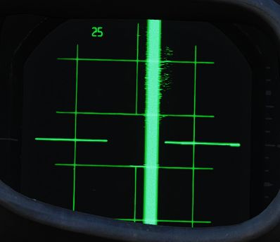
The back bias amplifier in the radar produces a noise signal based on the overall strength of the echoes. Once this noise signal exceeds some threshold, the system will consider it a jamming condition and enter Home On Jam. The range track circuit goes into memory mode, the angle track circuit continues to operate and track the jamming target in elevation and azimuth.
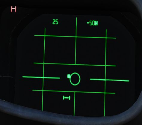
The Home On Jam condition is also indicated by the engraved H on the WSO DSCG and the last zero digit of the closure velocity is replaced by a H along with the closure rate flashing.
Spotlight
In the 100 and 200 mile ranges, a procedure known as Spotlight can be used to maintain radar monitoring of a target manually.
Spotlighting entails placing the acquisition cursor over the desired return, then selecting and holding the full action trigger position of the Antenna Hand Controller. Doing so, the antenna will nutate and revert to the chosen Polar Switch selection to increase target definition, but without attempting the automatic lock-on.
The target can be maintained in a well-observable state by holding full action and following the target-return with the Antenna Hand Controller until it reaches a range at which lock-on can be achieved (with the applicable change in range setting; the radar cannot attempt a lock at an incompatible range setting).
Intercept Computations
The LRU-1 Intercept Computer can calculate firing envelopes for the Sparrow and Sidewinder Missiles.
Range Strobes
The DSCG can display two range strobes at any given time representing the missile envelope. There are three possible strobe types.
| Range Indication | Description |
|---|---|
| Rmax | Maximum range of the missile provided the target continues flying on current heading and course. |
| Rmax2 | Maximum range of the missile if the target performs the shortest high g turn to tail aspect. |
| Rmin | Minimum range capability of the missile. |
| Missile Selected | Strobes Displayed |
|---|---|
| Sparrow | Rmax and Rmax2 |
| Sidewinder | Rmax and Rmin |
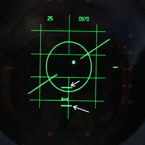
All ranges are calculated for the point the Trigger is pressed and hold down for release, not the point where the actual release signal is send a few seconds later. This means if the missile envelope is met on the display, then the Trigger can be pressed and the envelope will be valid for missile launch.
Allowable Steering Error (ASE) Circle
The allowable steering error indicates the maximum lead or lag at which the missile can be launched and will still retain a high probability of hit. The circle diameter gradually increases in size once Rmax is reached and gradually begins decreasing in size as the target range approaches Rmin.
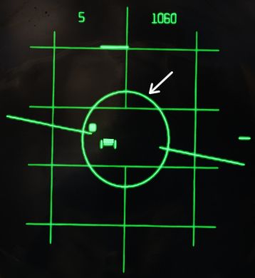
With the Sparrow selected, the max ASE Circle size is 25 degrees for an AIM-7E and 35 degrees for an AIM-7F.
With the Sidewinder selected, if caged, the ASE Circle size is fixed at 1.2 degrees. With it un-caged the ASE Circle dynamically changes size as described above, with the max diameter representing 25 degrees.
Aim Dot
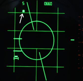
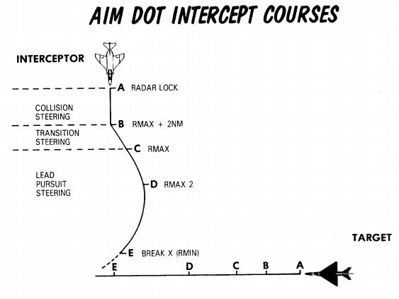
The aim dot provides steering commands to the pilot. There are three different types:
- Collision Steering, this minimizes time to intercept by putting the fighter on an intercept course.
- Transition steering, this begins 2 nmi outside Rmax and steers the aircraft towards the next steering type.
- Lead pursuit, inside Rmax lead pursuit minimizes the missile's post-launch maneuvers.
Shoot/In Range Lights
Shoot Lights illuminate provided the following conditions are met:
- Aim Dot is Inside the ASE Circle
- Target is within Rmax and Rmin
If Sparrows are selected then shoot lights are also inhibited when the target aspect is 90 ±9 degrees (left or right) and the target is lower than 5 degrees above the horizon. This prevents shooting a Sparrow into the main lobe clutter.
💡 With the Flight Instrument Brightness Knob out of its fully CCW position - such as during flights at night, all SHOOT lights will remain off.
Hold Altitude Light
The Hold Altitude Light illuminates provided the following conditions are met:
- Range is greater than the computed snap-up range.
- Altitude is greater than 32,000 ft.
- The target is more than 8000 feet above the fighter.
When the light is illuminated the azimuth error in the aim dot should be corrected only when the light goes out. The fighter should snap up to center the aim dot.
Break X
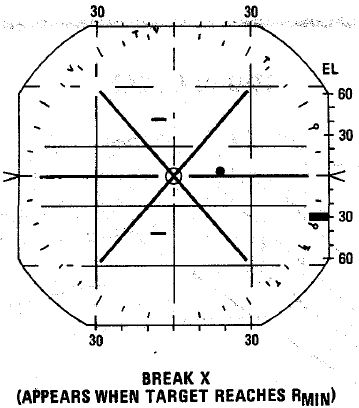
In all modes (except VI) when the target is lower in range than the calculated Rmin the Break X symbol will be displayed to indicate minimum range condition.
In Visual Intercept (VI) break X is displayed when range is less than 1000 ft.
When break X is displayed, the ASE Circle is also removed.
Firing Interlocks
There are several interlocks to prevent firing missiles in unfavorable conditions.
For the Sidewinder the only interlock preventing the missile from being fired is with the flaps in the down position.
For the Sparrow there are several conditions:
- The aim dot must be within the ASE Circle
- The in range and shoot lights must be on
- There must be no break X condition
- The selected mode must not be Visual Intercept
💡 Note that SHOOT lights remain off with the Flight Instrument Brightness Knob out of its fully CCW position. The firing interlocks are not influenced by this.
The interlocks are overridden automatically with a HOJ condition or when the Sparrow is to be fired in boresight mode. The interlocks can be overridden manually with the Interlock Switch.
Boresight and Cage Condition
Boresight
Boresight can be entered either by moving the Mode Knob to BST or by depressing the CAGE button on the throttle. The latter enters a cage condition which is very similar to boresight entered through BST, with the exception that the cage condition limits the range to 5 nmi and forces the maneuver setting into the HI position.
When in boresight, the antenna is fixed along the radar boresight line and the radar returns are displayed on the scope as in an acquisition mode. Acquisition can be commanded with half action as in automatic search to acquire, and then full action can be used to initiate track. Range and angle tracking will begin as normal.
Sparrows can be fired without tracking the target. If that is the case, the pilot must position the target on the gunsight pipper and the WSO can select an appropriate aspect setting. The Sparrow can now be fired.
💡 Targets need to be within a 5-degree zone, or an attempted lock will likely result in a bad lock.
Cage Condition
The cage condition is a close combat mode which can be entered at any time by depressing the CAGE Button on the pilot throttle. This, by default, puts the radar into boresight as described above.
When the cage condition is present, the following changes happen:
- Air-To-Air light in the rear pit illuminates.
- Trigger control is transferred to the air-to-air weapons (including when ARM and TV are selected)
- Optical sight switches into the A/A mode.
- Computer Automatic Acquisition becomes available.
If a track condition exists before the CAGE Button is pressed and the pinky switch on the throttle is in RADAR or HEAT, the radar breaks track and returns to boresight. If the pinky switch is in GUNS, the lock is not broken.
Cage mode can be exited from either cockpit. The pilot can place the Weapon Select Knob into or out of the B position. If the pilot leaves the Weapon Select Knob in B, it does not preclude a later entry into Cage mode. The WSO can exit cage mode by pressing the Air To Air Button.
Computer Automatic Acquisition Mode (CAA)
Once in Cage mode, the radar can be selected into Computer Automatic Acquisition using the Nose Gear Steering button on the stick.
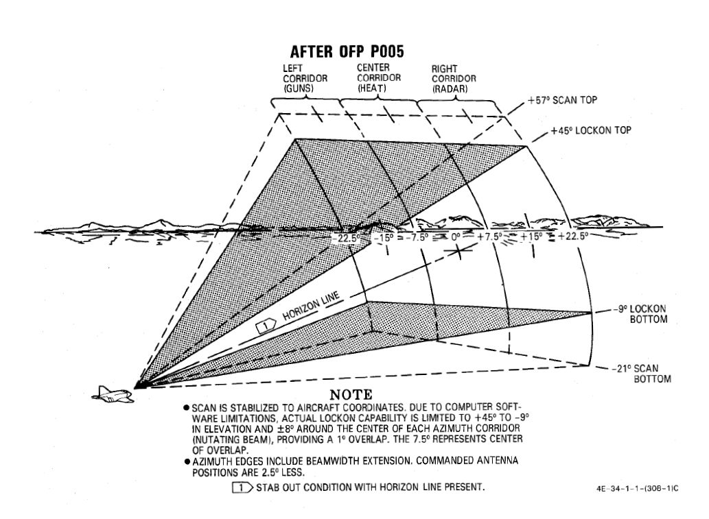
In CAA, the radar enters a vertical-oriented scan pattern 78 degrees in height by 15 degrees wide, the scan is 3 vertical bars wide. Actual radar lock capability within this scan pattern is from +45 degrees above the horizon line to -9 degrees below the horizon line due to APQ software limitation. In the event that the radar finds a suitable target within the scan volume, the target will be locked. Should the flight crew find the locked target not be the one intended, the Nose Gear Steering button can be pressed on either stick grip to return the radar back to the search pattern.
In CAA mode, the radar’s search pattern can be shifted left and right utilizing the pinky switch on the throttle.
| Pinky Selection | Scan Center |
|---|---|
| Guns | Left (-15 deg) |
| Heat | Center (0 deg) |
| Radar | Right (+15 deg) |
To exit CAA, the pilot can select position B on the Weapon Select Knob, or the WSO can push the Air-To-Air button. Should a radar lock be in place at the time of mode exit, it will be retained.