General Radar Operation
Magnetron and Klystron
The magnetron and klystron are the two methods for producing radio frequency energy in the APQ-120 radar set. Both, the magnetron and klystron radiation is fed through the antenna and emitted from the feedhorn.
Magnetron
The magnetron is the main radio frequency emitter for the radar. It produces pulsed energy which is used to detect and track targets.
Magnetron emission is only present when the Radar Power Knob is in OPER or EMER and all interlocks described below are satisfied.
The magnetron is protected by a wave guide pressure switch and a temperature interlock. If either of these interlocks are open (possibly because of damage or malfunction) the Radar Power Knob can be moved into EMER to return operation; however, operation of the magnetron without adequate pressure or cooling, may damage the magnetron and can burn the feedhorn.
The magnetron is not powered until 3 minutes after radar is turned on. This can be overridden by moving the Radar Power Knob into EMER; however, operating the magnetron without sufficient warm up may result in incorrect pulse width and timing and/or degraded pulse power.
Klystron
The klystron produces continuous wave radio frequency energy, which is used to tune and guide the Sparrows.
The klystron emissions are present when the Radar Power Knob is in STBY, OPER or EMER, the Radar Missile Power Switch is in CW and all interlocks described below are satisfied.
The klystron is protected by two temperature switches, a pressure switch and a surge current switch. If any of these interlocks (with the exception of the surge current switch) are open, the Radar Power Knob can be moved into EMER to return operation; however, damage to the klystron and feedhorn may result.
The klystron is not powered until 100 seconds after the radar is turned on. This can be overridden by moving the Radar Power Knob into EMER; however, operating the klystron without sufficient warm up may result in degraded power.
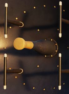
Feedhorn Nutation
Feedhorn nutation is required for automatic tracking. The feedhorn nutates to rotate the radiated energy around the antenna axis. This modulates the radar echoes. Where the echo is strongest the antenna will steer if tracking, this drives the antenna back onto a tracked target.
A side-effect of this nutation is increasing the beam-width, from 3.7 degrees (half power) to 6.7 degrees (full power) while reducing the average intensity of the beam.
Below describes the nutation settings for the action switch.
| Mode Knob | Range Knob | Action Switch | Nutation |
|---|---|---|---|
| RDR, BST, AIR-GND | ALL | Release | ✅ |
| MAP | ALL | Release | ❌ |
| MAP-PPI | ALL | Half or Full Action | ❌ |
| RDR, MAP-B, BST, AIR-GND | AI | Half or Full Action | ✅ |
| Not AI | Half Action | ✅ | |
| Full Action | ❌ |
Antenna Stabilization
There are three antenna stabilization modes. Two apply to Air-To-Air Operation and the other to Air-To-Ground Operation.
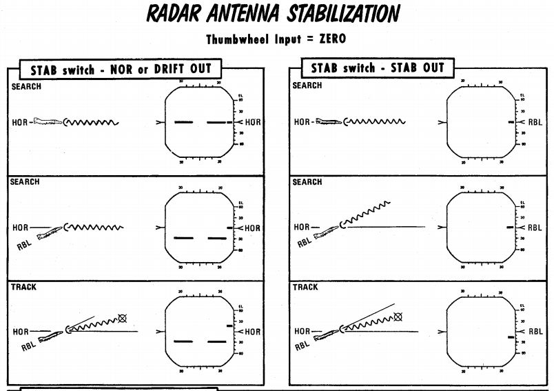
NOR
Normal operation of the antenna stabilization.
In Automatic Search, the antenna is stabilized in pitch and roll to the horizon (radar plane). The center of the radar scan is along the heading of the aircraft. In this mode the zero degree mark on the display indicates the horizon.
In Air-To-Ground Ranging, the antenna is boresighted to the radar boresight line but stabilized in drift.
DRIFT OUT
The same as NOR, but drift stabilization is removed.
STAB OUT
In Automatic Search the antenna does not stabilize to the horizon, but instead th aircraft reference.
With Air-To-Ground Ranging, the antenna is boresighted to the radar boresight line without drift stabilization. In this mode the zero degree mark on the display indicates the radar boresight line.
Pulse Setting
The pulse setting determines several characteristics of the Radar Set. These include the length of the transmitted pulse, which amplifier is used to amplify the signals, the frequency at which the pulses are emitted (i.e. the pulse repetition frequency).
The setting is controlled with the Pulse Switch into either LONG or SHORT modes.
| Mode | Amplifier | Pulse Repetition Frequency (PRF) Setting (Hz) | Pulse Length (microseconds) |
|---|---|---|---|
| LONG | Narrow Band | 370 | 2.0 |
| SHORT | Back Bias | 1060 | 0.4 |
💡 The AIR-GND and Automatic Acquisition mode force the pulse setting into SHORT.
The AUTO setting enables the power-level mode switching (PLMS) described below.
Power Level Mode Switching
Power Level Mode Switching automatically selects the LONG or SHORT, and Narrow Band or Back Bias amplifiers depending on several conditions such as target range, echo strength or noise signal.
Gain Control
The amplification of the signals that enter the receiver is called the gain. The gain setting is important to both search and tracking operations and is the main means for the crew to pickup targets on the display.
Manual Gain Control
The gain can be altered manually. This changes how returns are displayed. Higher gain settings amplify all echoes but can result in noise and saturation resulting in degraded image. Lower gain settings will result in better target contrast; however, weaker returns will not be visible, this can degrade detection range.
| Too much gain | Perfect gain (2 targets) |
|---|---|
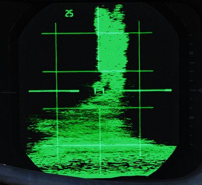 | 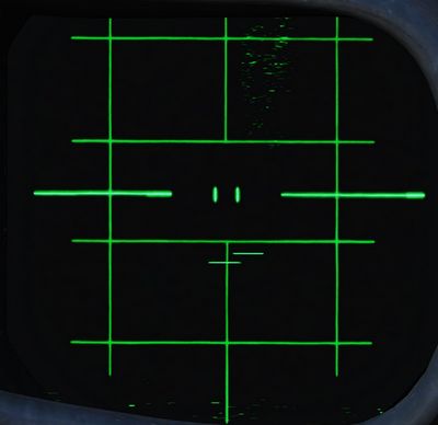 |
When the radar locks on a target, the gain control is switched to the Automatic Gain Control Circuit and manual gain control no longer is used.
💡 Getting the correct gain is a balance and comes with experience, as a general rule of thumb for search the gain should be increased until a small amount of noise (random specks) begins to show.
Along with receiver gain the display also has image levelling, after adjusting the gain it may take a few scans for the image to adjust the level correctly.
Automatic Gain Control
The Automatic Gain Control takes control of the gain setting once the radar is in track. The gain is adjusted automatically using the target within the range tracking gate to provide a consistent target signal for tracking.
Sensitivity Time Control (STC)
The strength of a radar echo falls off with 1 / r^4 where r is the
range. This means on a normal display the brightness of the radar returns will
get dimmer with distance.
For ground mapping the APQ-120 counteracts this effect. With the Radar Mode Knob in MAP and the Display Knob in a PPI mode, Sensitivity Time Control is enabled.
When enabled, it exponentially increases the receiver gain with range to counteract the echo power fall off with range. This provides an approximately even brightness with increasing range.