Center Section
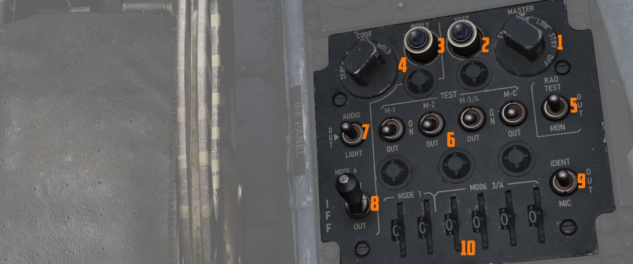
The center area of the right console contains IFF and lighting controls.
IFF Control Panel

As opposed to the Interrogator panel in the WSO cockpit, this panel provides the pilot with the ability to adjust the IFF transponder of their own aircraft. Which would then be picked up by interrogators in other aircraft.
💡 Due to engine limitations, the settings on the panel have no effect for DCS. However, they are exposed to external tools, such as SRS.
For further explanation, see the IFF System controls chapter.
Master switch
The master switch (
| Position | Operation |
|---|---|
| Off | Identification system de-energized. |
| STBY | Full Power supplied to the system but with interrogations blocked. |
| LOW | System operates with reduced sensitivity. |
| NORM | System operates at full sensitivity. |
| EMER | Allows the system to respond to interrogations in Modes 1, 2 and 3/A. The reply for Modes 1 and 2 is a special emergency signal of the codes selected on the applicable dials, while Mode 3/A replies are special emergency signals of code 7700. |
Mode 1 Selector Switch
The three position Mode 1 Selector switch (
| Position | Operation |
|---|---|
| M-1 | Self test position (Inoperative) |
| ON | Enables Mode 1 for operation. |
| Out | Disables Mode 1 |
Mode 2 Selector Switch
The three position Mode 2 Selector switch (
| Position | Operation |
|---|---|
| M-2 | Self-test position. Light illuminates if Mode is operating properly. |
| ON | Enables Mode 2 for operation. |
| Out | Disables Mode 2 |
Mode 3/A Selector Switch
The three position Mode 3/A Selector switch (
| Position | Operation |
|---|---|
| M-3/A | Self-test position. Light illuminates if Mode is operating properly. |
| ON | Enables Mode 3/A for operation. |
| Out | Disables Mode 3/A |
Mode C Selector Switch
The three position Mode C Selector switch (
| Position | Operation |
|---|---|
| M-C | Self test position (Inoperative) |
| ON | Enables Mode C for operation. |
| Out | Disables Mode C |
Mode 1 and Mode 3/A Code selectors
The Mode 1 code selector (
Mode 4 Selector Switch
The two position Mode 4 Selector switch (
| Position | Operation |
|---|---|
| ON | Enables Mode 4 for Operation. |
| Out | Inhibits Mode 4 from replying. If Mode 4 code is inserted, an interrogation will cause the IFF warning light and the MASTER CAUTION light to come on momentarily. |
Mode 4 Indication Switch
The Mode 4 indication switch (
In the AUDIO position, an audio signal indicates reception of Mode 4 interrogations, and the Mode 4 REPLY light illuminates during transmissions. In the LIGHT position, the Mode 4 REPLY light illuminates when Mode 4 replies are transmitted, and audio is not present. In the OUT position, both light and audio indications are inactive.
To test the press-to-test Mode 4 reply indicator light, the indication switch must be in the AUDIO or LIGHT position.
Mode 4 Function Switch
The Mode 4 function switch (
In the A position, the transponder responds to Mode 4 interrogations with the same setting as set in the A position, and in the B position, it responds to interrogations with the same code setting as set in the B position. If the switch is in the wrong position for the code being interrogated (e.g., in A with B interrogation), the IFF warning light and MASTER CAUTION light will not activate.
💡 Code settings for A and B positions are inserted before flight and can be zeroed by placing the switch to ZERO.
The HOLD position is not used in flight but retains the code setting if another flight is anticipated during the code period. Momentarily positioning the switch to HOLD after landing, waiting 15 seconds, and then turning off the IFF master switch and radar power knob retains the code with the power off.
Illumination of the IFF warning light and MASTER CAUTION light can be caused by internal component failure, failure to respond to a valid interrogation, or a zeroized code.
Monitor-Radiation Test Switch
This switch (
Identification of Position Switch
The Identification switch (
| Position | Operation |
|---|---|
| IDENT | Allows the system to respond with identification of position replies in all modes that are being used. The response is continued for a 15 to 30 seconds duration after the switch is released. |
| OUT | Disables identification of position capability. |
| MIC | Same as positioning the switch to IDENT, except that the UHF microphone button must be used to trigger the identification. |
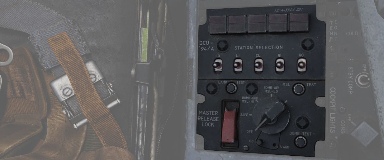
DCU-94A Stores Control-Monitor Panel

This panel is used to control and test the separate release circuit system for nuclear stores.
Nuclear stores are separated from the regular release system to prevent accidental release.
💡 This is not simulated in-game.
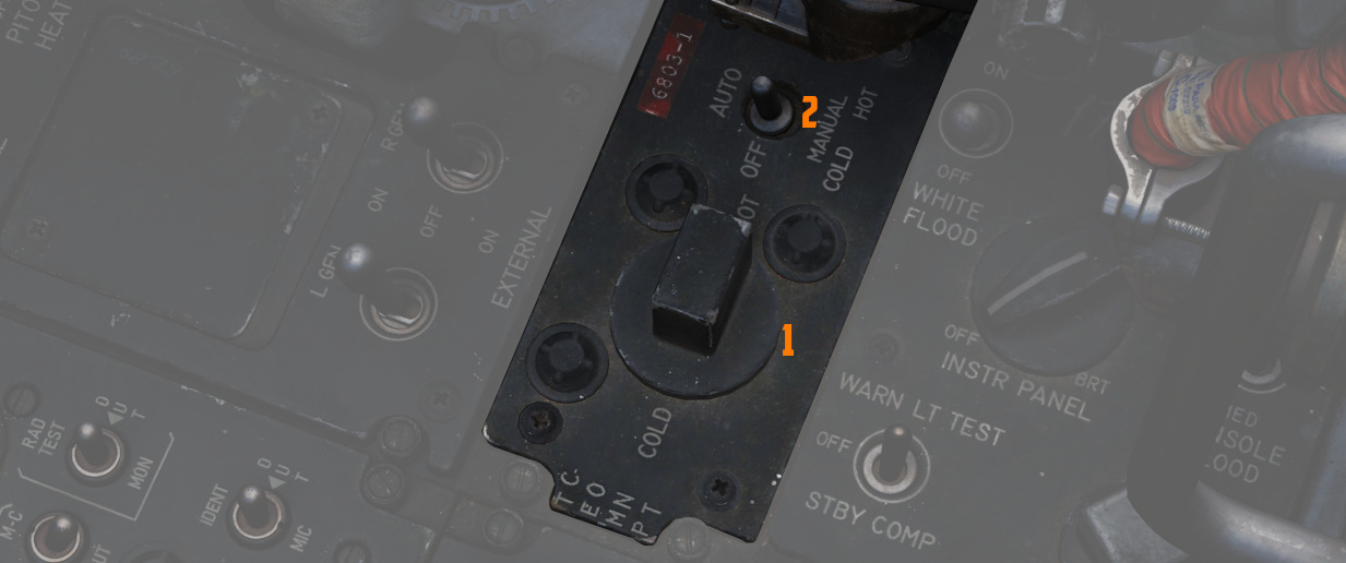
Temperature Control

The knob (
Should the AUTO system fail, the switch can be placed in either a manual mode.
The center position of the switch turns the system off.
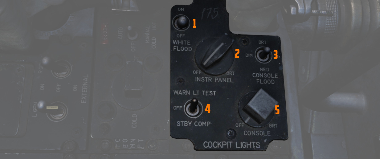
Cockpit Lighting Control Panel

The Cockpit Lighting Control Panel provides control of all panel edge lighting, flight instrument panel lighting, the console floodlights, the white floodlights found under the canopy sill over each console, and also includes the Warning Light Test/Standby Compass Light switch.
For further information about lighting, see the lighting chapter.
White Floodlight
The White Floodlight switch (
Instrument Panel Knob
This knob (
💡 The main flight instruments are controlled via the Flight Instrument Brightness Knob instead.
Console Knob
The Console Light Control Knob (
Console Floodlight
This switch (
💡 To turn them off, place the switch in DIM and the Console Knob in OFF.
💡 Floodlights for the Instrument Panel are found on the right wall.
Warning Light Test Switch
The Warning Light Test Switch (
In the STBY COMP position, it illuminates the light for the Standby Compass.
Both functions are deactivated when the switch is placed in the OFF position.