Front Section
The front section of the right console is dominated by communication and navigation controls.
Master Caution Reset
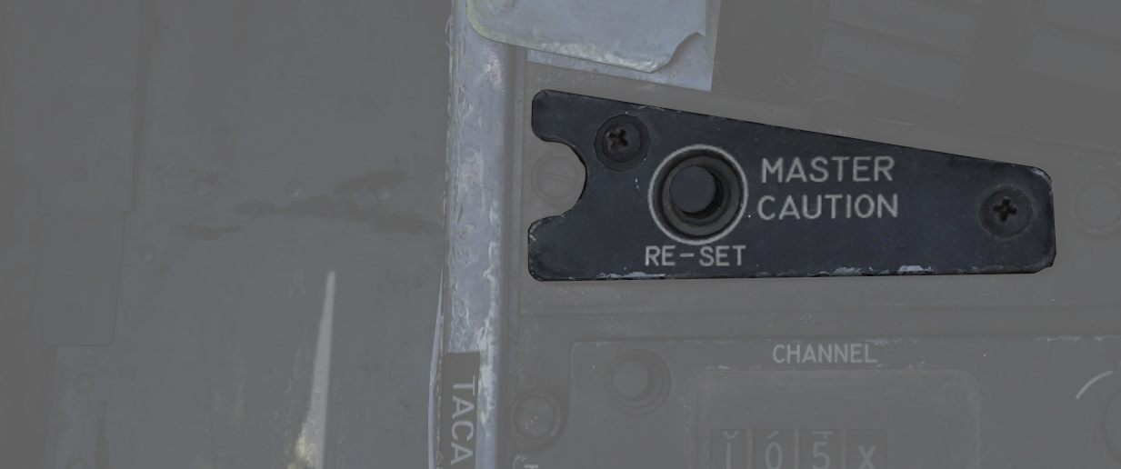
Used to extinguish telelight panel warnings and the Master Caution warning lamp once the necessary action has been taken. In the event a fault has not been effectively corrected, pressing the Master Caution Reset button will not turn the respective warning off.
TACAN Control Panel
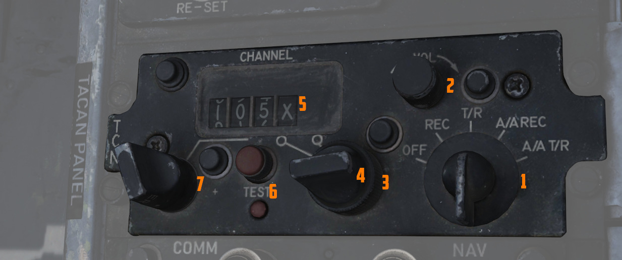
The TACAN Control Panel is used to enter the desired TACAN channel, mode, and audible volume for the monitoring of said channel by the aircrew. The panel is duplicated in both cockpits, and the panel in command of the TACAN receiver is toggled by the NAV CMD button of the Communication Control Panel.
Channel Knobs
On the control panel there are two Navigation Channel Control knobs (7,4 and 3), with the
left (
Test Button and Lamp
Between these two knobs is the TEST button (
The lamp above the button illuminates to indicate test status.
See 7.19.4 Navigation test chapter for further information.
Volume Knob
To the upper right, the VOL knob (
Function Selector
The TACAN Function Selector Knob (
| Name | Description |
|---|---|
| OFF | The TACAN receiver is de-energized and offline. |
| REC | The TACAN receiver is active, providing bearing information on the HSI, BDHI, and ADI. |
| T/R | Both the receive and transmit functions of the TACAN are active, which provide bearing and nautical mile range information for the HSI and BDHI. |
| A/A REC | The TACAN receiver decodes bearing information from compliant aircraft for the HSI, BDHI, and ADI steering display. |
| A/A TR | The TACAN receiver receives both bearing and slant range information in nautical miles from the transmitting aircraft, providing this on the HSI and BDHI. |
💡 Air to Air TACAN functionality requires the channel to be set 63 channels above or below the cooperating aircraft, but on the same range- X or Y. So a tanker on 123Y should be set to 60Y in the F-4.
Communication Control Panel
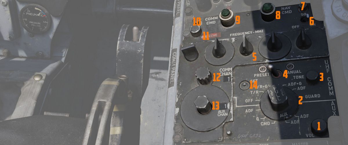
The Communication Control Panel provides the selection and mode of the UHF radio in the aircraft.
Command Buttons
The panel is duplicated in both cockpits, and control over the
radio is changed by pushing the COMM CMD Button (
Radio Volume
Beneath the COMM CMD button is the radio volume (
Squelch Switch
Close to the NAV CMD button is the Squelch switch (
Frequency and Channels
The A-3-2-T Selector knob (
💡 Due to engine limitations, modes A and T, belonging to the HAVE-Quick functionality, are not simulated.
The four Frequency Selection Knobs work in concert with the A-3-2-T knob and Preset/Manual switch. Frequencies are entered beginning with the 3 or 2 selection on the A-3-2-T Selector, and can be entered from 225.00 to 399.975 MHz in increments of 0.025. With Preset/Manual in the Manual position, the UHF radio is directly set to the displayed channel. In the Preset position, the set channels can be entered into the COMM CHAN memory, with the desired position selected with the Comm Channel Control knob - the smaller knob to the left of the Preset/Manual switch, and displayed in the COMM CHAN window. Channels are stored in the displayed channel preset with the SET pushbutton. Once stored, channels are directly selected using the Comm Channel Control knob with the Preset/Manual switch in the Preset position.
Directly underneath the Comm Channel Control Knob is the Aux Channel Knob (
The Aux Volume Control knob (
The Set button (
Tone Button
The Tone Pushbutton (
💡 Due to engine limitations, the tone button, belonging to the HAVE-Quick functionality, is not simulated.
Comm Function Selector
The Comm Function Selector Knob (
| Name | Description |
|---|---|
| OFF | All UHF Radios off. |
| T/R ADF | Comm receiver - comm reception. |
| Comm transmitter - comm transmission. | |
| Comm guard receiver - standby. | |
| Aux receiver - ADF reception. | |
| T/R+G ADF | Comm receiver - comm reception. |
| Comm transmitter - comm transmission. | |
| Comm guard receiver - guard reception. | |
| Aux receiver - ADF reception. | |
| ADF+G CMD | Comm receiver - ADF reception. |
| Comm transmitter - comm transmission. ADF interrupted during transmission. | |
| Comm guard receiver - guard reception on ADF antenna. | |
| Aux receiver - comm reception. | |
| ADF+G | Comm receiver - ADF reception. |
| Comm transmitter - comm transmission. ADF interrupted during transmission. | |
| Comm guard receiver - standby. | |
| Aux receiver - guard reception. | |
| Guard ADF | Comm receiver - guard reception. |
| Comm transmitter - guard transmission. | |
| Comm guard receiver - standby. | |
| Aux receiver - ADF reception. |
Utility Panel (Right)
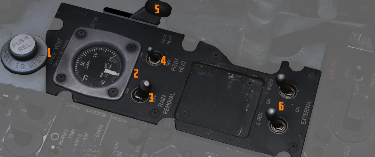
The utility panel features an emergency vent handle for releasing overpressure in the cockpit. Furthermore, it features the Defog/Foot Heat Lever as well as the Generator control switches.
Cooling Reset Button
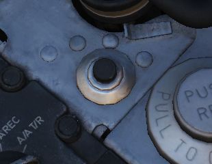
Resets the CNI cooling system.
Cockpit Pressure
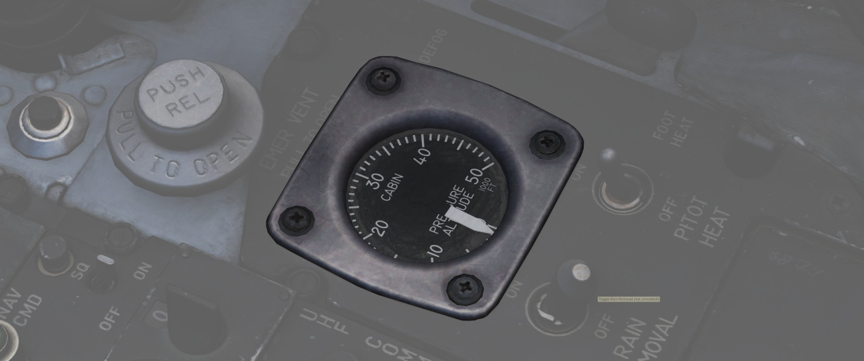
Cockpit Altitude Gauge
Displays the current pressure inside the cockpit as a means of equivalent effective cabin altitude above mean sea level in thousands of feet.
That is, if the gauge (
To prevent sickness and hypoxia, the pressure should be observed and oxygen supply adjusted accordingly:
| Pressure Range | Description |
|---|---|
| below 13000 ft | Breath regular air |
| 13000 ft - 40000 ft | Breath Oxygen through mask |
| 40000 ft - 62000 ft | Breath pressurized Oxygen through mask |
| above 62000 ft | Need to wear a pressure suit (not available) |
See Oxygen Chapter for more information.
Emergency Vent Handle
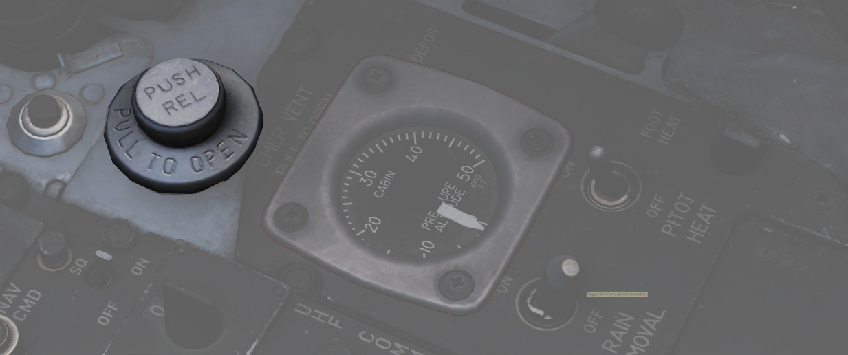
A plug (
Without pressurization, the effective cabin altitude will be identical to the current altitude. Which, if flying at high altitudes, can result in hypoxia.
It should only be used if the pressurization system is malfunctioning and reads abnormal values, or to eliminate smoke and fumes from the cockpit. Descend to safe altitudes before activating.
Defog/Foot Heat Lever
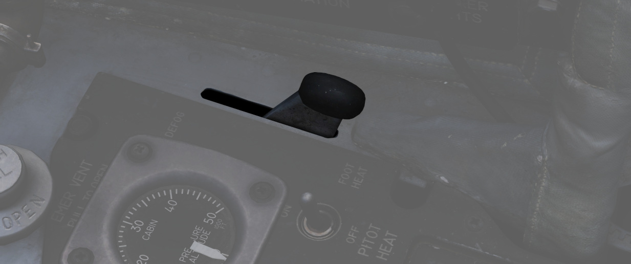
The Defog/Foot Heat lever (
It is possible, through selection of cold temperature settings, particularly on humid days, for the air conditioning system to deliver air at temperatures well below the dew-point, with resultant cockpit fogging. This fog can be dissipated by selecting a slightly warmer temperature.
When operating in high humidity conditions, it is recommended that a temperature warmer than normal is selected, prior to starting the takeoff run, to preclude the possibility of cockpit fogging as thrust is increased. Should cockpit fogging occur, the quickest means of eliminating this condition is by activating the emergency vent knob.
During cruise operations, prior to letdown, place the temperature control knob in the 2 o’clock position and the Defog/Foot Heat Lever to defog, to increase the defog temperature for the windshield and canopy preheating. For airplanes without slats, if the flaps are lowered for letdown and fogging persists, retract the flaps or increase power (use speed brakes as necessary to maintain airspeed) to provide higher defogging air flow.
Rain Removal Switch
If the two-position switch (
The system should not be used during dry conditions, as the hot air will heat up the windshield. If the glass reaches critical temperatures, the WINDSHIELD TEMP HI warning on the telelight panel will illuminate. In this case, the switch should be turned OFF immediately.
Pitot Heat Switch
With the pitot heat switch (
For normal operations, this should always be activated prior to takeoff. But not left ON while on the ground for longer than one minute to prevent damage due to overheating.
See 3.1.1 Pitot-Static System for details.
Generator Control Switches
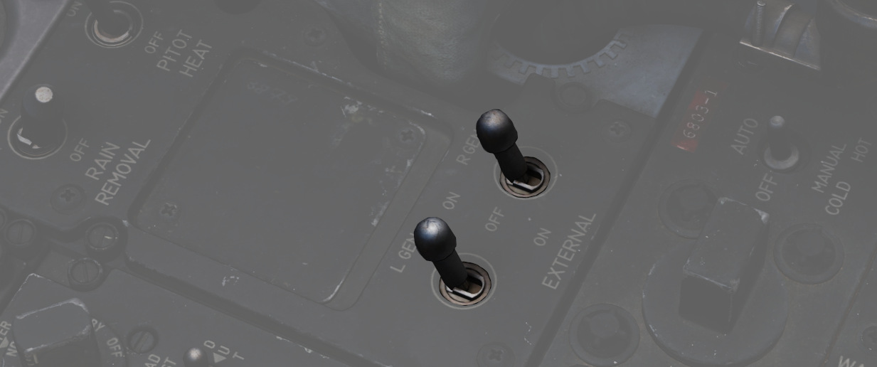
The 2 two position switches (
| Name | Description |
|---|---|
| ON | Generator is driven by the constant speed drive unit and applied to electrical bus. |
| OFF | Generator is offline. |
| ON (EXTERNAL) | External power is supplied through generator bus connection for pre-startup needs. |
For further information, see the 3.8 Electrics chapter.