Left Sub-Panel
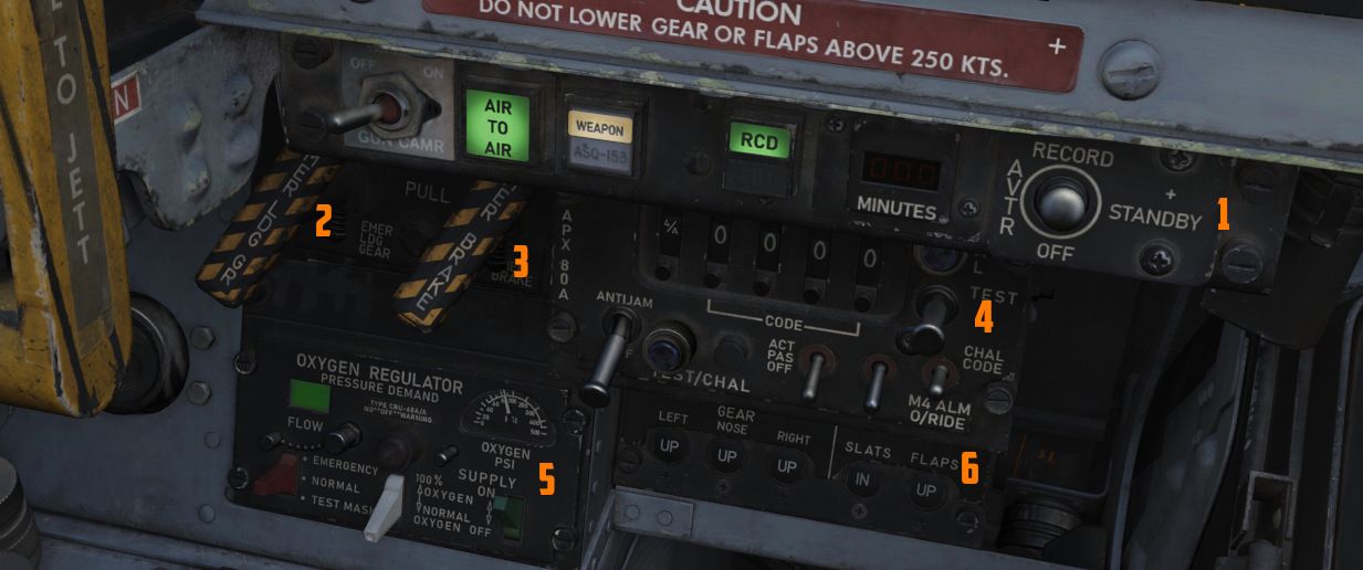
The left sub-panel contains the AVTR, Gun Camera, air-to-air indicators (
Gun Camera Switch
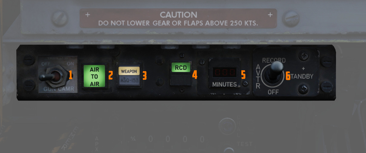
The two-position switch (
Air to Air Light
Illuminates (
Video Select Button
Push button (
AVTR Control
Controls the Airborne Video Tape recorder system, which records the intercom sound, as well as the rear radar screen.
For further information about the Recorder system, see 9.6 Recorder.
AVTR Switch
With the switch (
AVTR Tape Timer
The cassette can record up to 20 minutes of footage, indicated in the small
display (
EOT Light
Once the end of the tape has been reached, the EOT light (4 lower half) illuminates and the tape must be unthreaded before it can record again.
RCD Light
Lit (
Emergency Landing Gear Handle
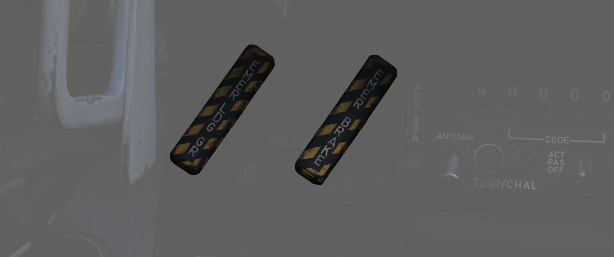
Deploys the landing gear using a pair of compressed air bottles; the handle cannot retract gear, only deploy it in an emergency.
Emergency Brake Handle
In an emergency, it discharges a portion of the brake system's hydraulic accumulator to provide emergency braking. Contains a limited number of applications.
APX-80 Control Panel
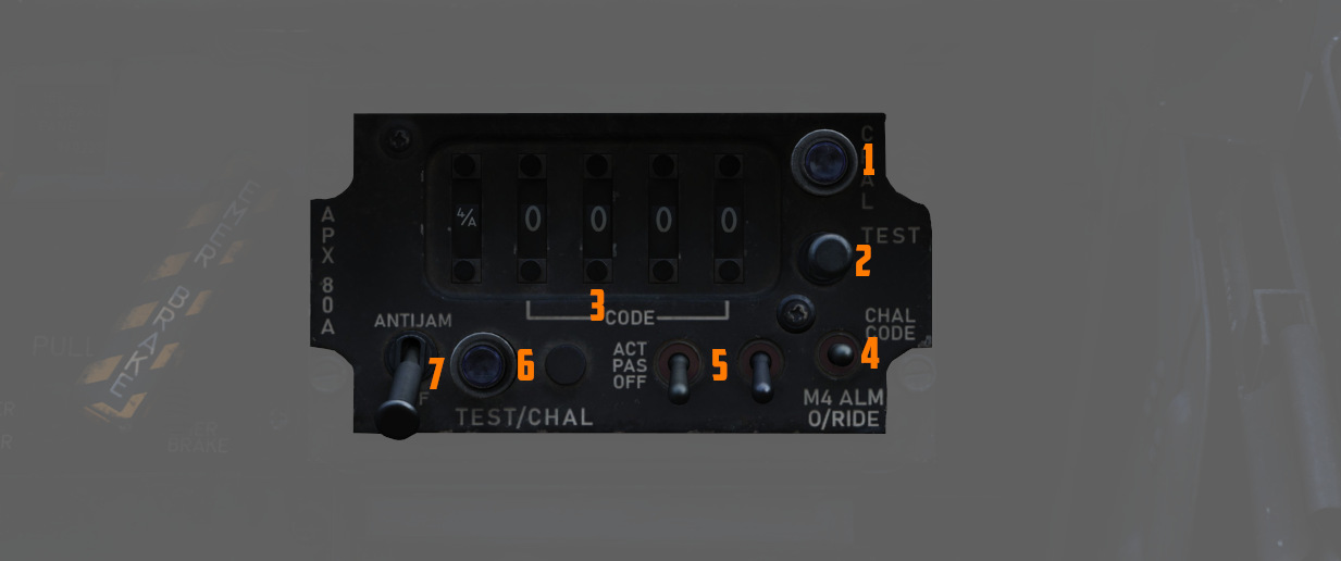
The AN/APX-80 combines the IFF Interrogator System APX-76 and the Combat-Tree system APX-81A. It is used to identify whether an aircraft is friendly or hostile.
See Interrogator Systems for details.
Code Buttons
The first digit of the code display (
- Off (white square)
- Mode 1
- Mode 2
- Mode 3
- Mode 4/A
- Mode 4/B
💡 In DCS, only Mode 4 (either A or B) is effective and can be used for interrogation.
The other four digits are used to set the IFF code to interrogate for Mode 1 to 3.
The buttons below and above the display are used to decrement and increment the corresponding setting, respectively.
Challenge Lamp
This dimmable push-to-test lamp (
Test/Challenge Code
Setting the switch (
TEST initiates a test of the system, see AN/APX-76 Test for details.
Anti-Jam
This switch (
Test/Challenge Lamp
This dimmable push-to-test lamp (
Test Button
The push button starts the built-in test of the APX-81A Combat-Tree system, see AN_APX-81A Test for details.
Mode 2
This switch (
The ACTIVE position is required to use the system.
Mode 3
This switch (
The ACTIVE position is required to use the system.
Mode 4
This switch (
This functionality was never installed and connected on this variant of the F-4E.
WSO Oxygen Regulator Panel
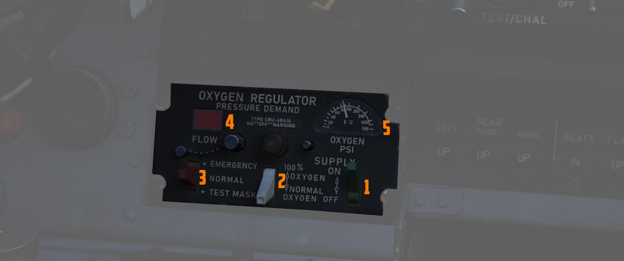
Supply Lever
Two-position switch (
Diluter Lever
A two position (
For a proportional amount of air to oxygen, the NORMAL OXYGEN position should be selected.
For pure oxygen, the 100% OXYGEN position should be selected. This setting is preferable if fire, toxic smoke or fumes occur in the cockpit.
Emergency Flow Control Switch
Three-position switch (
The Emergency Lever should remain in the center (NORMAL) position at all times, unless an unscheduled pressure increase is required.
Flow Indicator
Alternates (
Oxygen Pressure Gauge
Indicates (
For further information, see 3.7 Utility chapter, Oxygen section.
Landing Gear/Flap Indicator Panel
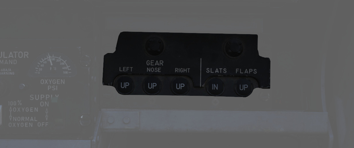
Displays current status of landing gear, flaps, and slat position.
Landing Gear
Status noted with the word UP (up), a barber pole illustration (in transition), or an icon of a wheel (down) relative to the current position.
See the 3.1.3 Landing gear chapter for more information.
Slats
Status noted with the words IN and OUT.
Flaps
Status noted with the word UP (flaps up) or DN (down). When transitioning, it may show a barber pole illustration. When transitioning back to the UP position, the indicator does not change until the flaps are fully retracted.
See the 3.1.2 FLight Controls & AFCS, Slats and Flaps section for more information.