The center section of the right console is dominated by the
WRCS panel for weapon delivery. For
more detailed information see the
WRCS chapter.

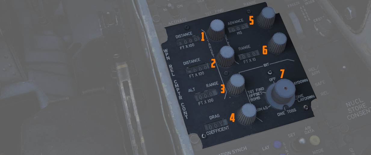
A pair of four position drum roller windows with matching analog knobs. The top
window (1) references distances in the North-South orientation (with
the first roller marked N/S), and the lower window (2) references
distances in the East-West orientation (with the first roller marked E/W).
The rollers reference the distance shown in increments of 100 feet, thus a
distance of offset in the East direction for 4000' would be entered as E0040.
The rollers do function in an analogue fashion, thus fractions of 100' can be
attained by moderating the last roller accordingly; as an example, a value of
250 feet would be attained with the space between the 2 and 3 value halfway in
the window in the last digit position.
A three position drum roller window (3) with matching analog knob
used to enter the altitude of either the Radar initial Point or the actual
target itself, and is referenced in increments of 100'. Fractional values can be
entered as described previously. This value can be changed once the Radar
Identification Point (RIP) or the Visual Identification Point (VIP) is properly
defined to increase release system accuracy.
A three position drum roller window (4) with matching analog knob
used to enter the drag coefficient value for the weapon being used from the
bombing tables for the intended release mode.
🚧 Lookup tables will soon be provided. However, the
bombing calculator provides working
solutions for all weapons regardless.
A three position drum roller window (5) with matching analog knob
used to advance the release signal given from the
WRCS to the fire control system
relative to the WRCS target point, in any duration from 0 to 999 milliseconds.
Also functions in conjunction with
ARBCS/LABS programmed release
timing.
This can be used to spread out a bombing run over a target area, for example, to
place the 3-th bomb of a 10-bomb salvo on the target.
The release advance control can be calculated with the
bombing calculator.
A three position drum roller window (6) with matching analog knob
used to manually set bomb range in accordance with the weapon's bomb release
schedule entry in the bomb tables.
The range can be calculated with the
bombing calculator.
A six position knob (7) utilized to perform BIT checks against the
individual WRCS delivery modes. The
BIT check is performed by selecting the desired mode for testing, pressing the
knob for five seconds, then pressing the Freeze button on the Cursor Control
Panel while keeping the BIT knob held down to confirm function.
See WRCS BITs for details.

Used for WRCS radar bombing mode
target entry. Functions only with
MAP-PPI mode selected
and applicable bombing mode selected on the
Delivery Mode Knob.
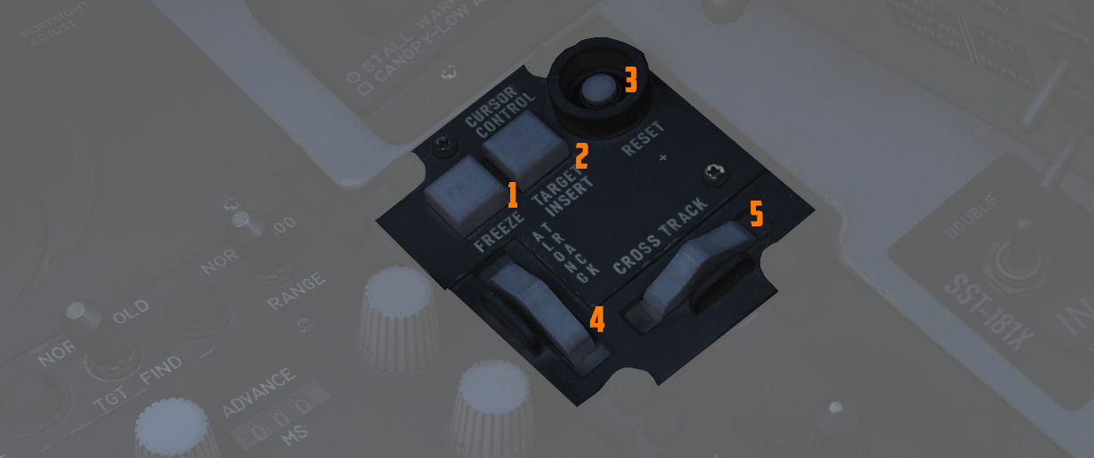
A push button (1) used in air to ground bombing with the
WRCS to initiate velocity tracking of
the aircraft from the INS, as well as
maintain a hold of the target position defined by the Along Track and Cross
Track cursor gates, thus defining the Radar initial Point. The button
illuminates and remains lit until the reset button is pressed, or another
delivery mode is selected.
A push button (2) that inserts the North-South and East-West offset
values entered into the WRCS control
panel into the WRCS computer,
performing the offset against the Radar initial Point defined by the Along Track
and Cross Track cursor gates and currently tracked with the Freeze Button. This
offset inclusion performs a shift of the Along Track and Cross Track cursors to
define the actual target defined by the
WRCS offsets on the radar scope. This
action initiates target steering information from the
WRCS to the navigational displays.
The Pave Spike system
also utilizes the Target Insert functionality for its Memory Mode.
Pressing the Reset Button (3) drops the currently tracked ground
target location from WRCS computer
memory, returns the Along and Cross Track cursors to their default positions,
and resets the velocity tracking system values to zero.
The Along Track wheel (4) is used to define the relative range of the
aircraft to the Radar initial Point, using an expanding/contracting hemisphere
cursor on the radar display. This hemisphere presents true range to the target
via the hemispherical PPI projection, thus allowing the Radar initial Point to
be detected in an offset approach to the target. Close approximation of range to
the Radar initial Point should be prepared first with the Along Track wheel
prior to using the Cross Track Wheel for best system accuracy- ie, the cursor
should be placed below the intended Radar initial Point return on the radar
scope, and the Cross Track wheel be brought to the return point.
The Cross Track wheel (5) is used to define the heading to the Radar
initial Point on the radar display in PPI mode, presented as a vertical line.
The intersection of the Along Track and Cross Track cursors defines the Radar
initial Point when the Freeze button is pressed.

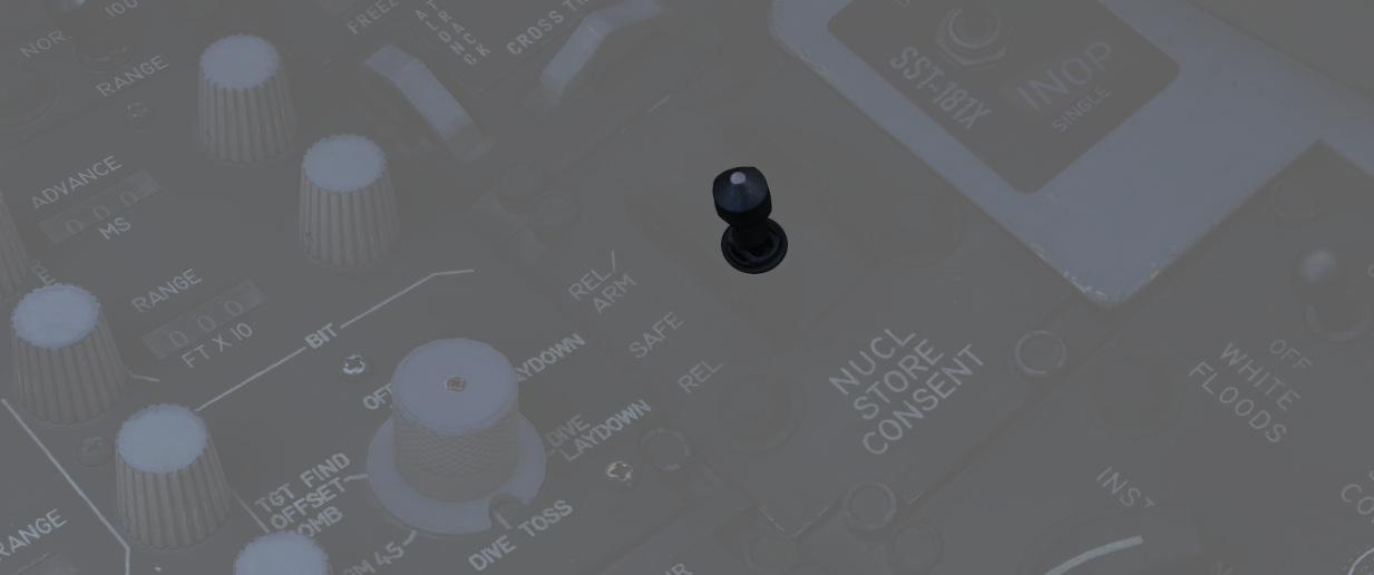
Used to arm nuclear stores. In the SAFE position, release is inhibited. REL
allows releasing stores unarmed, while REL/ARM allows dropping nuclear stores
armed.

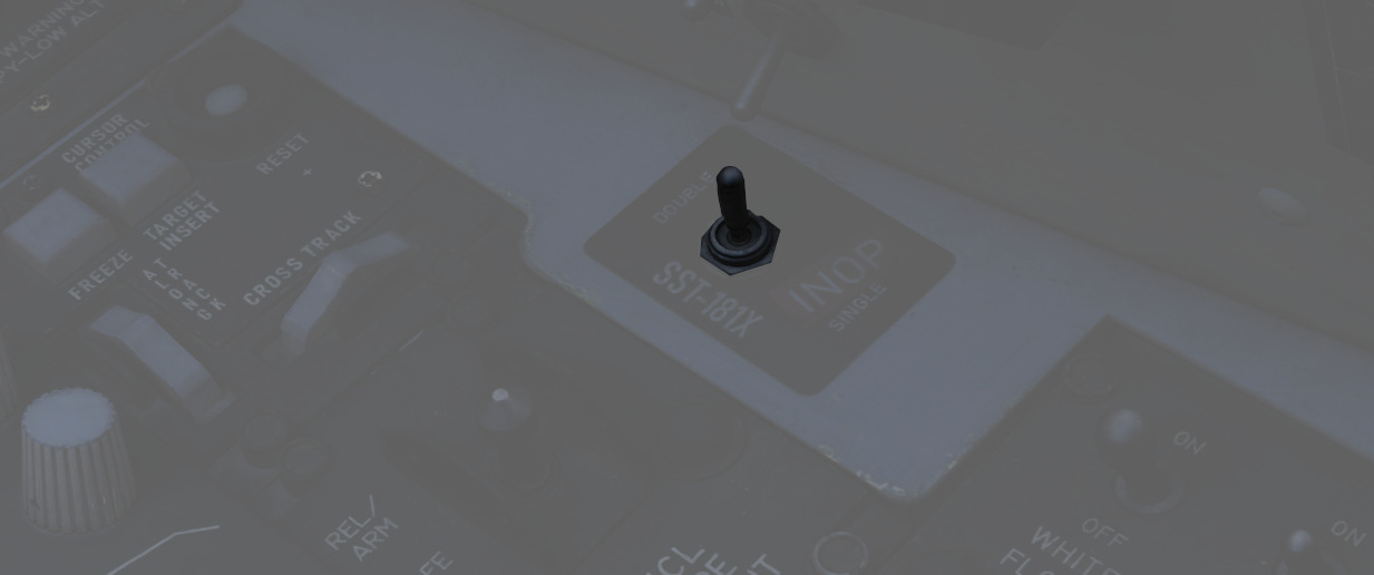
On the outer right side of the right console is a switch which would allow to
select the mode of the Combat Skyspot system used for ground-directed bombing.
The system was never installed on this variant of the F-4E.


