Front Section
The front area contains controls for weapon delivery and the INS.
Laser Coder Control
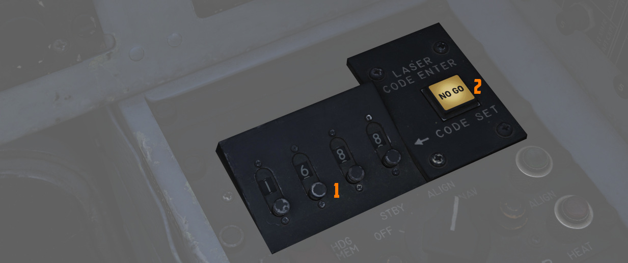
The WSO can set the laser code used by the targeting pod by using the four small push buttons on this panel.
Code Buttons
Each press (
Codes directly relate to laser frequencies, resulting in them having to be between 1111 and 1788 and not use digits 0 or 9 in order to be valid.
💡 Weapon laser codes can be adjusted in the Mission Editor or during rearming. The default code used is 1688.
Enter Button
Once a code has been set, it can be transferred to the Pave Spike by pressing
the ENTER button (
When power is applied to the system, it automatically initiates a transfer of the currently set code.
No Go Light
Validation of an entered code takes about 5 seconds. If the NO-GO light is lit, the code is invalid.
Inertial Navigation Control Panel
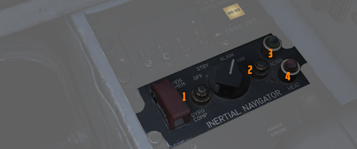
The Inertial Navigation Control Panel provides the rear pilot mode selection and system alignment command selection.
See 3.3.2 INS Navigation for further information.
Mode Selector Switch
The HDG MEM-GYRO COMP switch (
💡 Heading can be stored in the mission editor.
Power Control Knob
Knob positions (
| Name | Description |
|---|---|
| OFF | System off. |
| STBY | Power is applied to the heaters and temperature control system, and initiates Coarse alignment (if GYRO COMP is selected on the toggle). |
| ALIGN | Performs fine platform and gyro leveling and BATH (or HDG MEM) alignment. Then, if available, performs Gyro-compassing (Fine) Alignment. |
| NAV | Activates the INS for navigation function, performance of which is based on the alignment quality. |
HEAT Light
The HEAT Light (
ALIGN Light
The ALIGN Light (
Antenna Hand Control
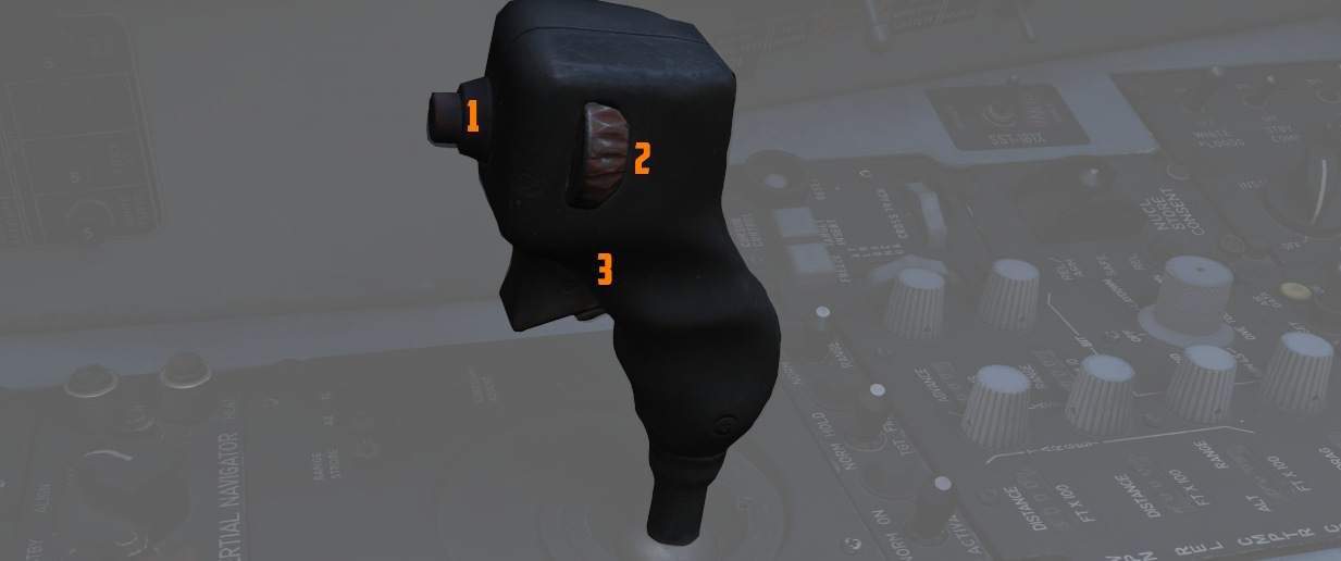
Joystick which integrates with the radar to perform range (fore and aft) and azimuth (left and right) positional control of the acquisition symbol on the radar display in the air-to-air modes, as well as the seeker/EO sensor direction with AGM-65 Maverick and Pave Spike.
Antenna Elevation Control
A thumbwheel (
Challenge Button
If controlling the radar, the button (
For the Pave Spike targeting pod, it instead toggles the field of view between WIDE and NARROW.
Action Switch (Trigger)
A 2-stage trigger (
Boresight Adjustment
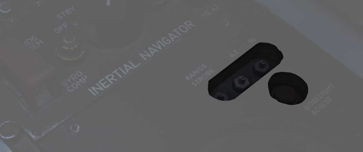
The boresight position of the antenna stick can be adjusted at its base using a screwdriver. Once set, the new values can be loaded by pressing the button below.
This is only accessible to ground crew personnel.
Weapon Delivery Panel
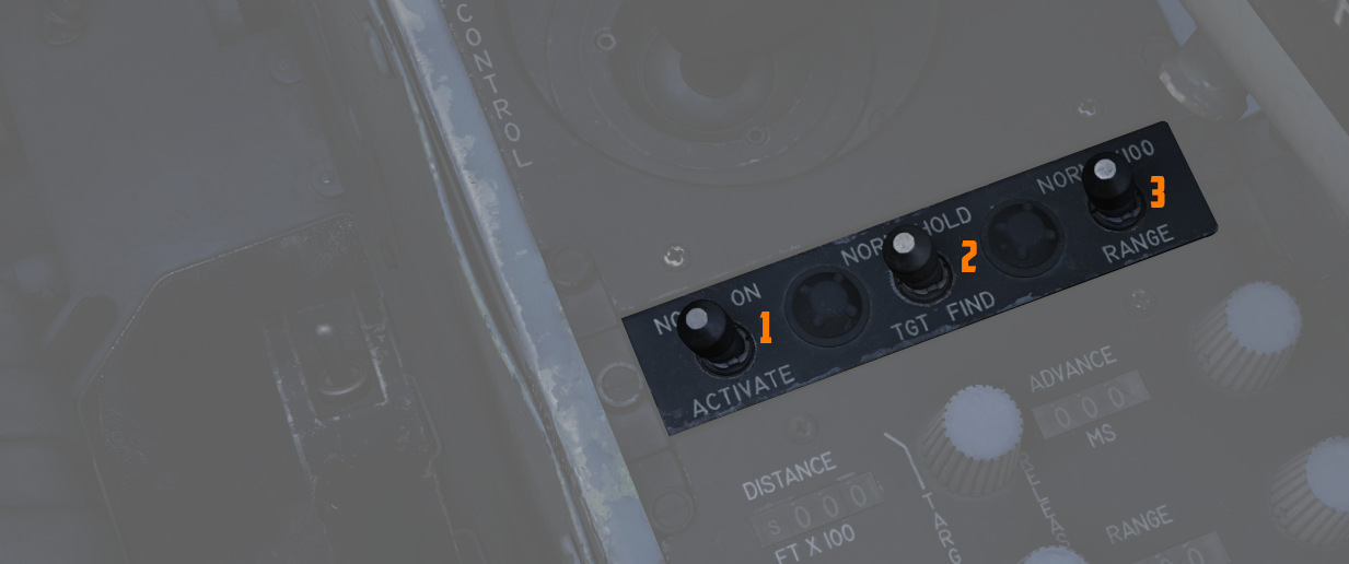
ACTIVATE Switch
The two-position switch (
TGT FIND Switch
The two-position switch (
RANGE Switch
Selecting x100 on the two position switch (
Volume Panel
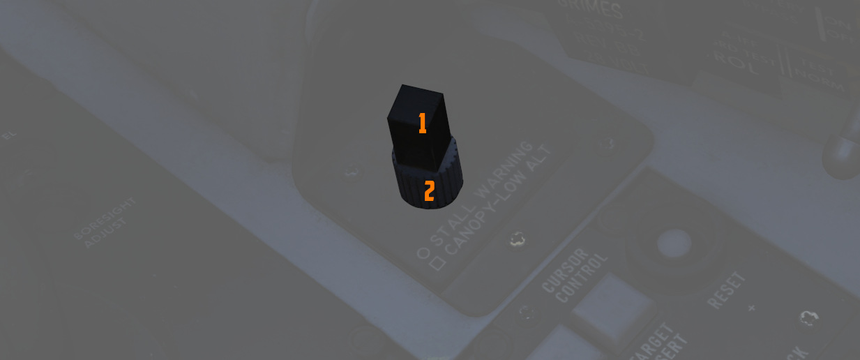
A small panel to the right of the antenna hand control stick contains two combined knobs to control volume.
Canopy/Low Altitude Warning
The cubic knob (
This system is not installed on this variant of the F-4E.
Stall Warning
The Stall Warning knob (
Under certain conditions, the system can override the volume to ensure the cue is always audible in dangerous situations.